Copyright © 1986-2026 by Sean Erik O'Connor. Permission is granted to copy, distribute and/or modify this document under the terms of the GNU Free Documentation License, Version 1.3 or any later version published by the Free Software Foundation; with no Invariant Sections, no Front-Cover Texts, and no Back-Cover Texts. A copy of the license is included in the section entitled GNU Free Documentation License
Getting Started with Blender
For Computer Generated Imagery (CGI) I use Blender. I'll work through examples of digital paintings I created in Blender illustrating a female model, trees, wine glasses, lakes, fences, hats, ocean, sun and outdoor scene lighting, huge objects, and backdrops.
Blender is free software, and can be downloaded for Mac OS, Ubuntu Linux and Windows, or built from source. Blender is super powerful and will take time to learn. Begin by watching the Blender 5.0 Beginner Donut Tutorial by Andrew Price, then follow his more advanced tutorials at Blender Guru. CG Cookie has advanced tutorials, e.g. Jonathan Williamson's Female Character Modeling series. For details, see the Blender User Manual. When you get stuck, search the web with google, look into user forums such as Blender Stack Exchange and Blender Artists.
Setup
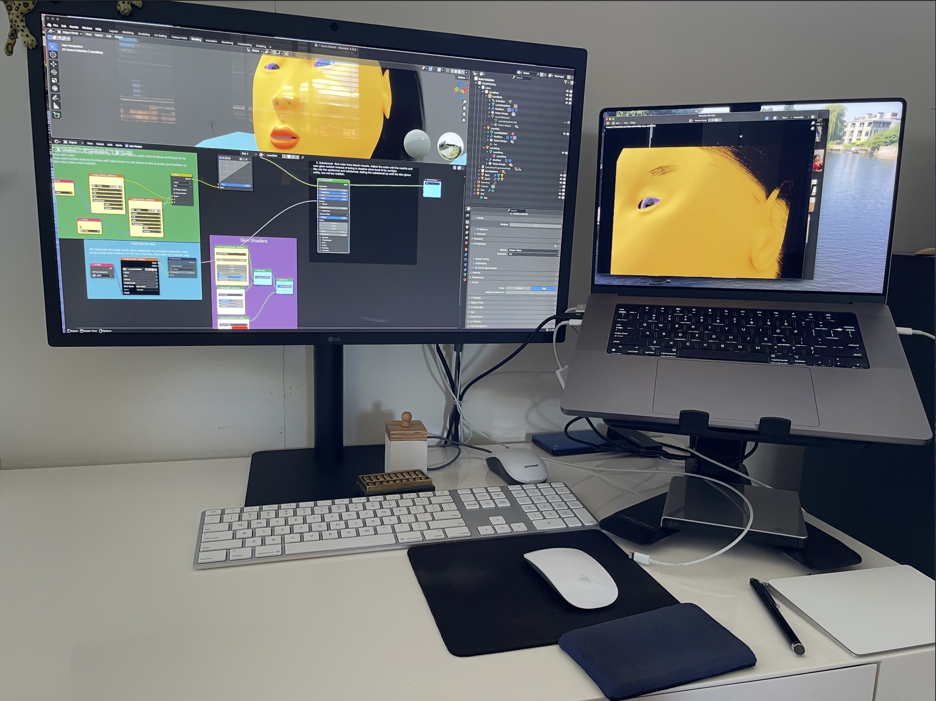
Here's my setup: a MacBook Pro laptop with a GPU, trackpad and two button mouse, a large 27" LG display for Blender, a 3 button mouse with scroll wheel, a desktop keyboard with numpad,
and a laptop screen to display tutorials or manuals.
Working Around Bugs
A few tips for working around bugs...
Reset to Factory Settings
Often, when upgrading to a new version of Blender, I found it avoids problems to start clean.
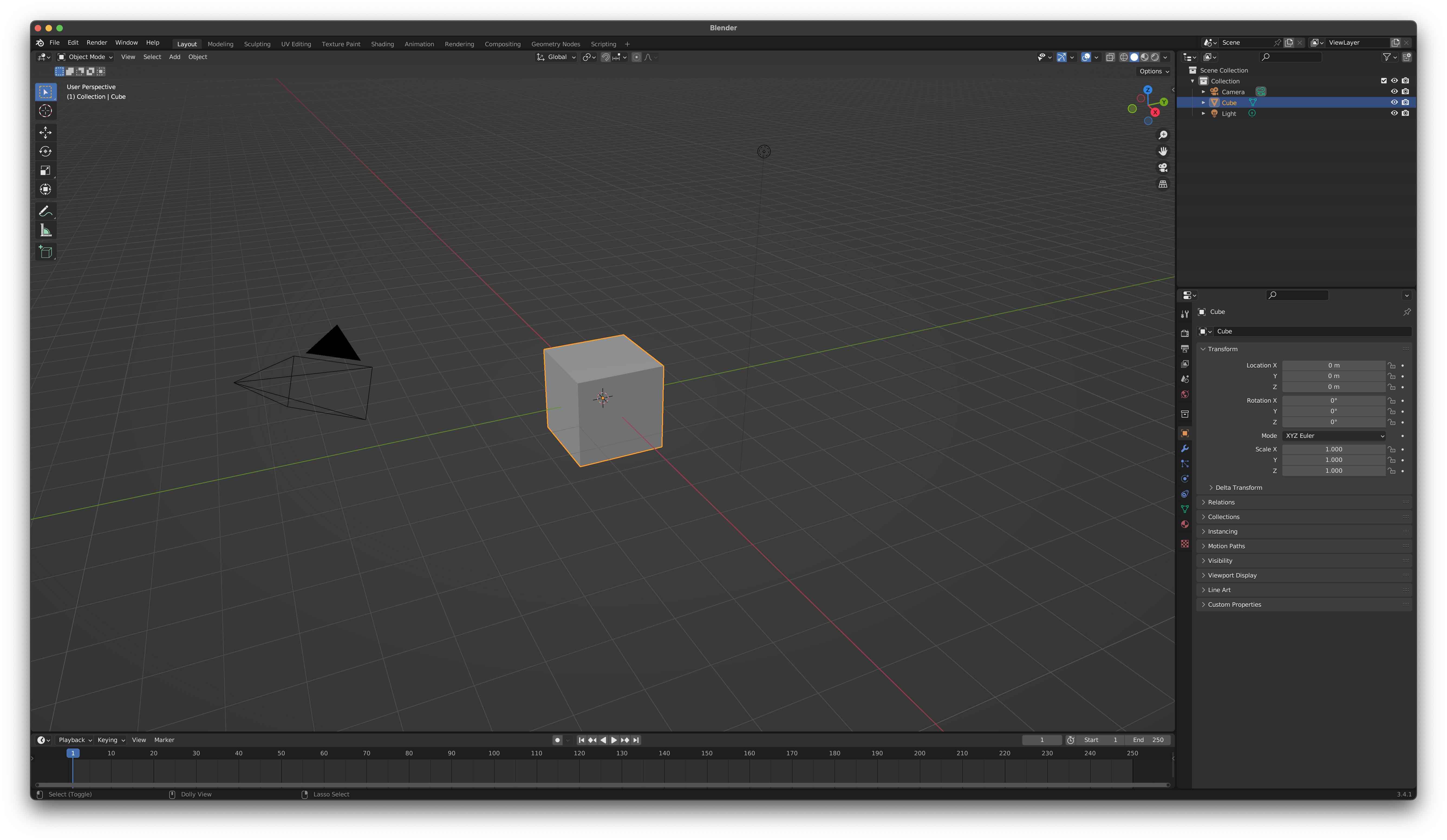
Generate the default cube view with
File ➤ New ➤ General,
then clear all settings to default with
File ➤ Defaults ➤ Load Factory Settings
You'll see the standard Blender interface:
Deleting Data and Starting Over
When using a major new version of Blender, you might have crashes and glitchy behaviour. You might be able to get back to a clean state as follows:
- Delete and reinstall Blender.
- Load default factory settings.
- Set up user preferences manually as above.
- Bring up the default cube scene, then select and delete the cube.
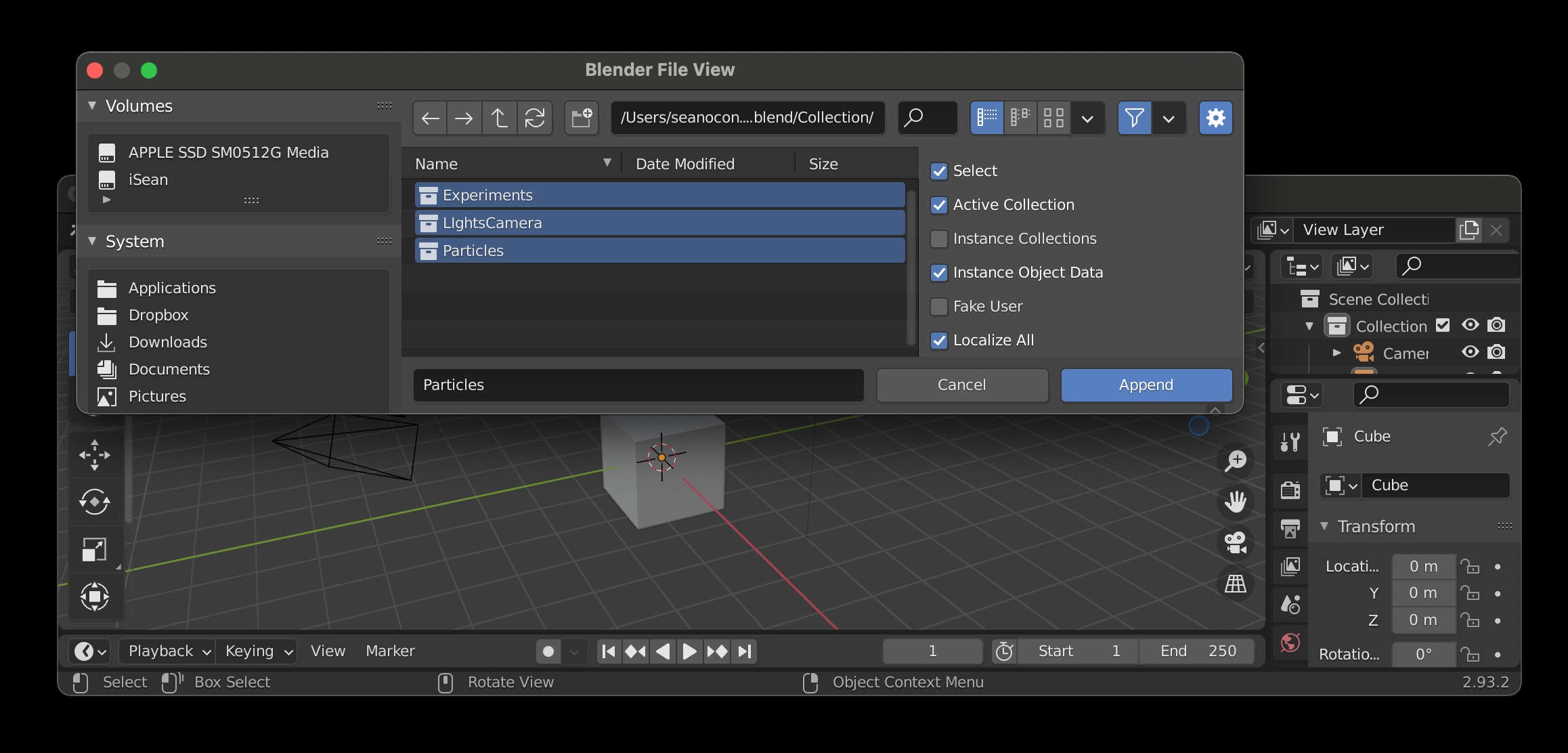
- Append from the .blend file as follows:
File ➤ Append Go through the directories and select the .blend file. In the Blend File View, go to Collection, select all items with A, then hit Append.
You might be missing some objects so add them as follows:
File ➤ Append, select the .blend file, go to
Object,
Shift Left Mouse Button to select all still missing objects, then hit Append
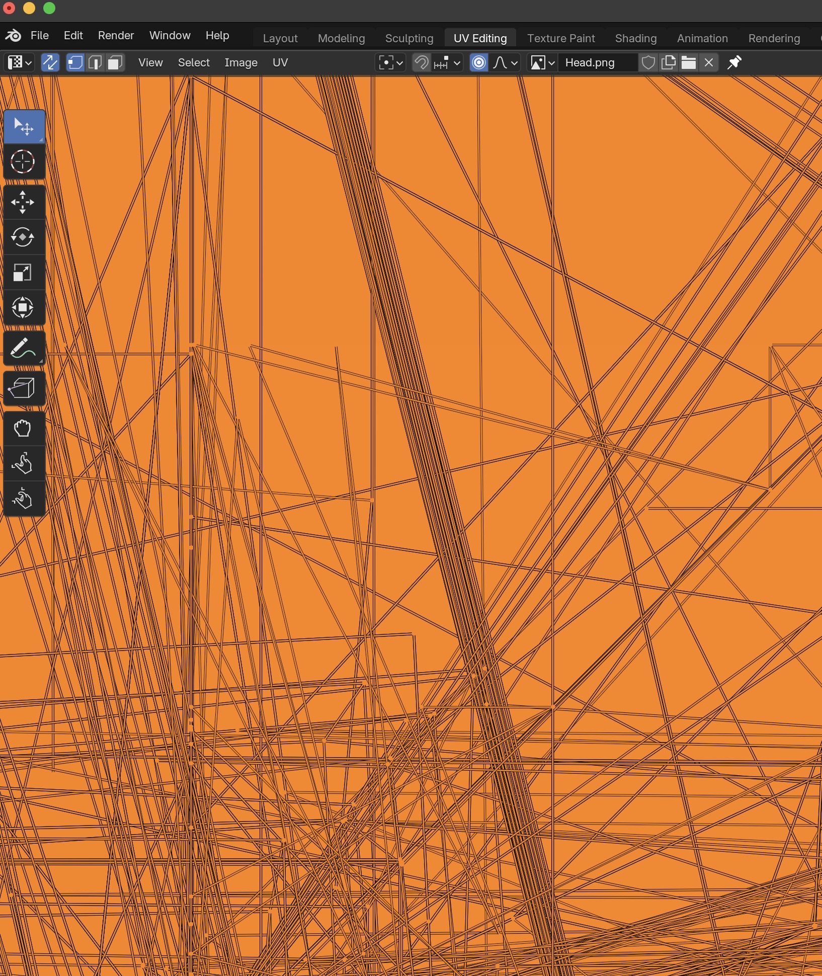
Here is a less extreme example of starting over from scratch: For example, I ran into a UV Editor bug
in a recent Blender version where the mesh was drawn incorrectly and then Blender crashed about half the time.
To fix it, I deleted my UV Maps for my model, reset the UV map, then did an unwrap from scratch. That fixed the crash.
Waiting for the Next Version
You can wait for the next release of Blender. For example, in version 4.3.2 on macOS, I rendered hair against an image backdrop in Cycles, but the hair was being sliced by the image; this was fixed in version 4.4.
User Settings
Let's tweak the settings for a Mac laptop.
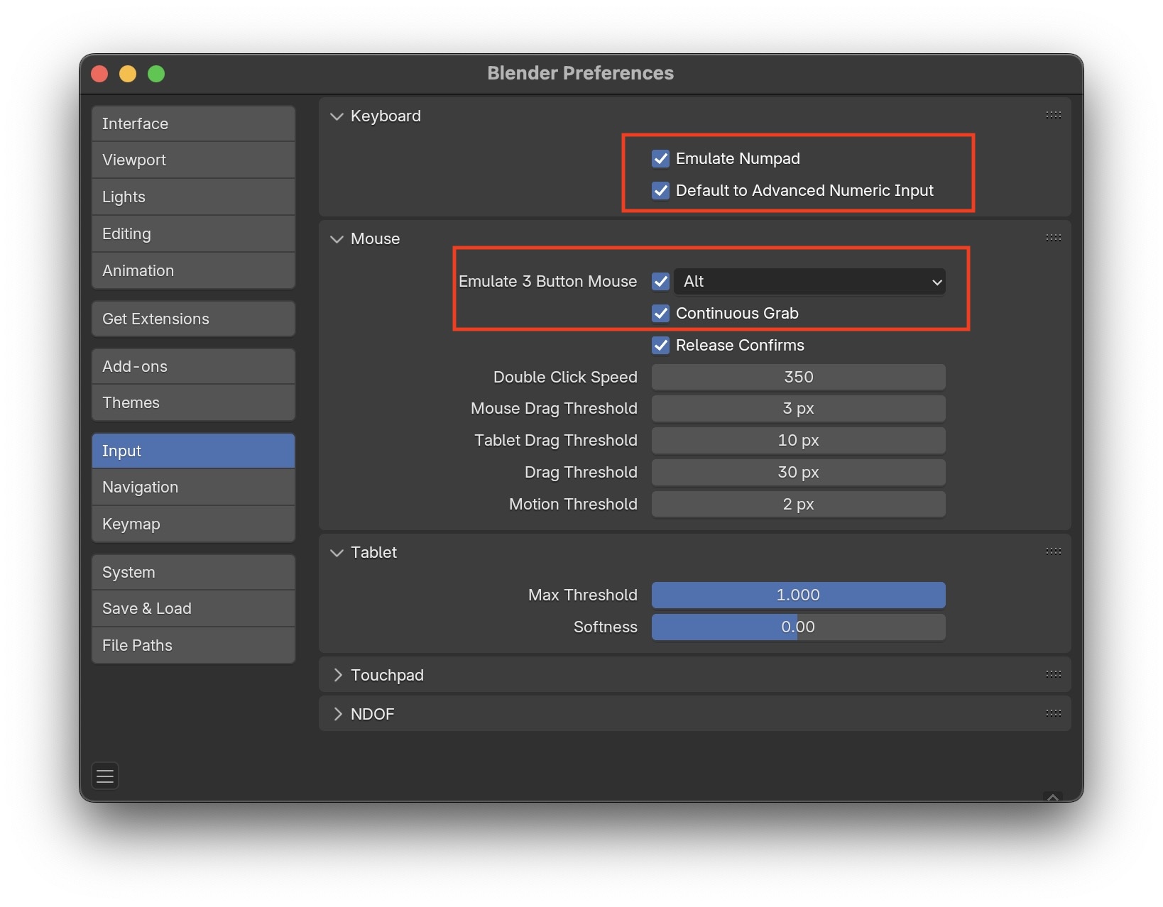
Go to Edit ➤ Preferences ➤ Input.
To use the laptop keyboard, click on Emulate Numpad which uses the
top row of number keys 0-9 on the laptop.
Click on Emulate 3 Button Mouse to simulate the middle button on a two
button mouse with Alt Left Mouse Button
In Edit ➤ Preferences ➤ Keymap set
Spacebar Action: to Search.
Enlarge the text a little by using a scale factor $> 1$ in
Edit ➤ Preferences ➤ Interface ➤ Display ➤
Resolution Scale = 1.15

Save the preferences when you are done.
File Path Settings and Hotkeys
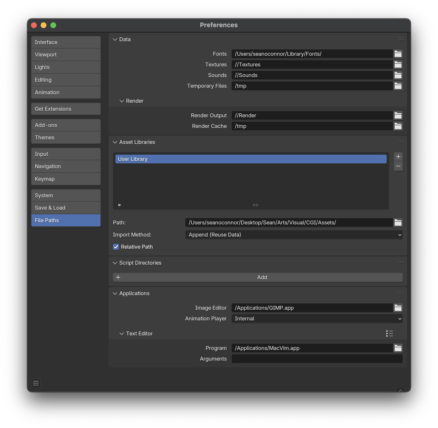
Set the file paths for each project in Edit ➤ Preferences ➤ File Paths The fonts are the Mac system fonts. Each project has directories of texture images, python scripts, sounds, and render results. Use double slash // for paths relative to the directory containing the .blend file. Gimp is my image editor.
I tried to use a relative path //Assets to save brushes on macOS,
but Blender gave an error message saying the files in the /Assets subdirectory were read only..
So I changed to an absolute path instead.
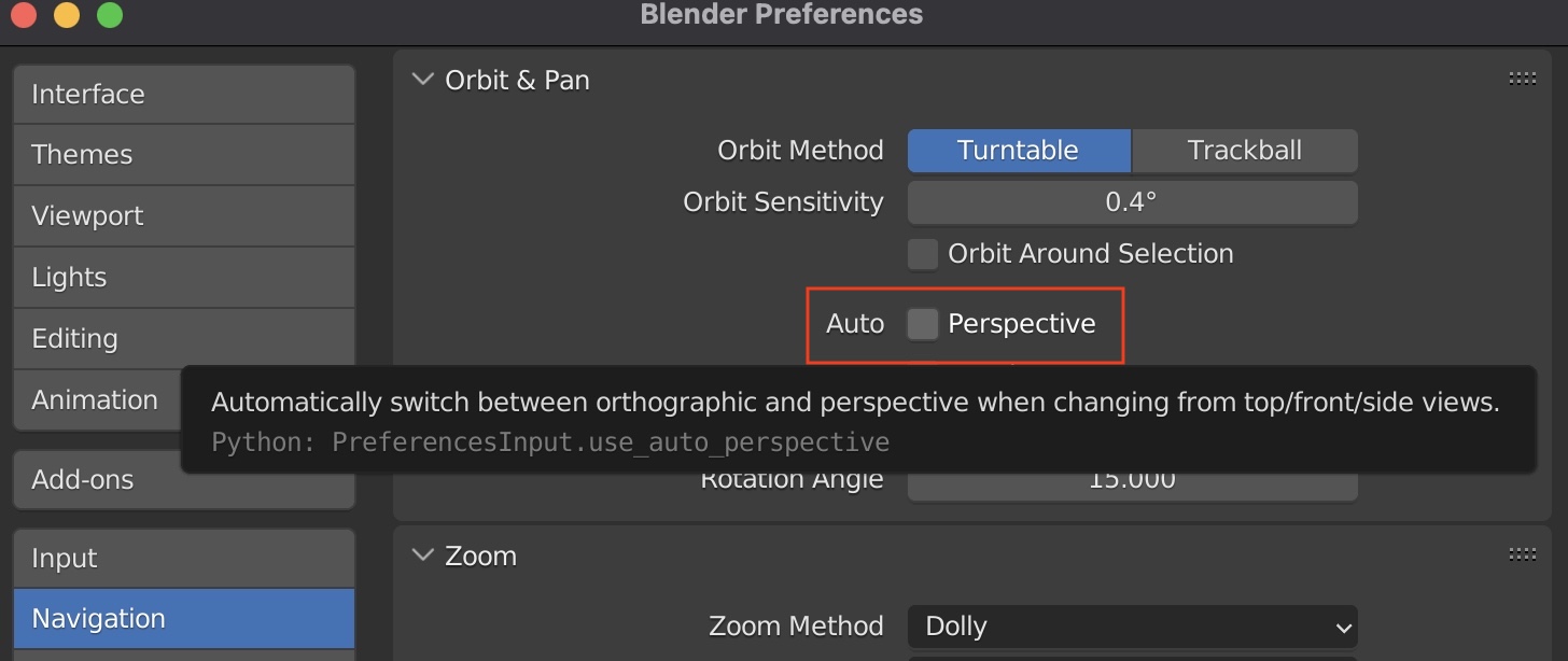
When switching views using the numpad keys 1 3 7 I noticed I was getting
dumped out of Perspective Mode into Ortho Mode. To stop this, go to
Edit ➤ Preferences ➤ Navigation ➤ Auto and turn off
Perspective
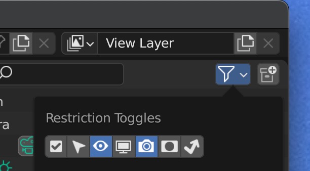
In the Outliner Panel, enable all of the restriction toggles.
They let you hide/show objects in the viewport and to enable/disable object renders.
Add-ons and Extensions
Add-ons
Add-ons help debug your artistry.
Go to Edit ➤ Preferences ➤ Add-ons ➤
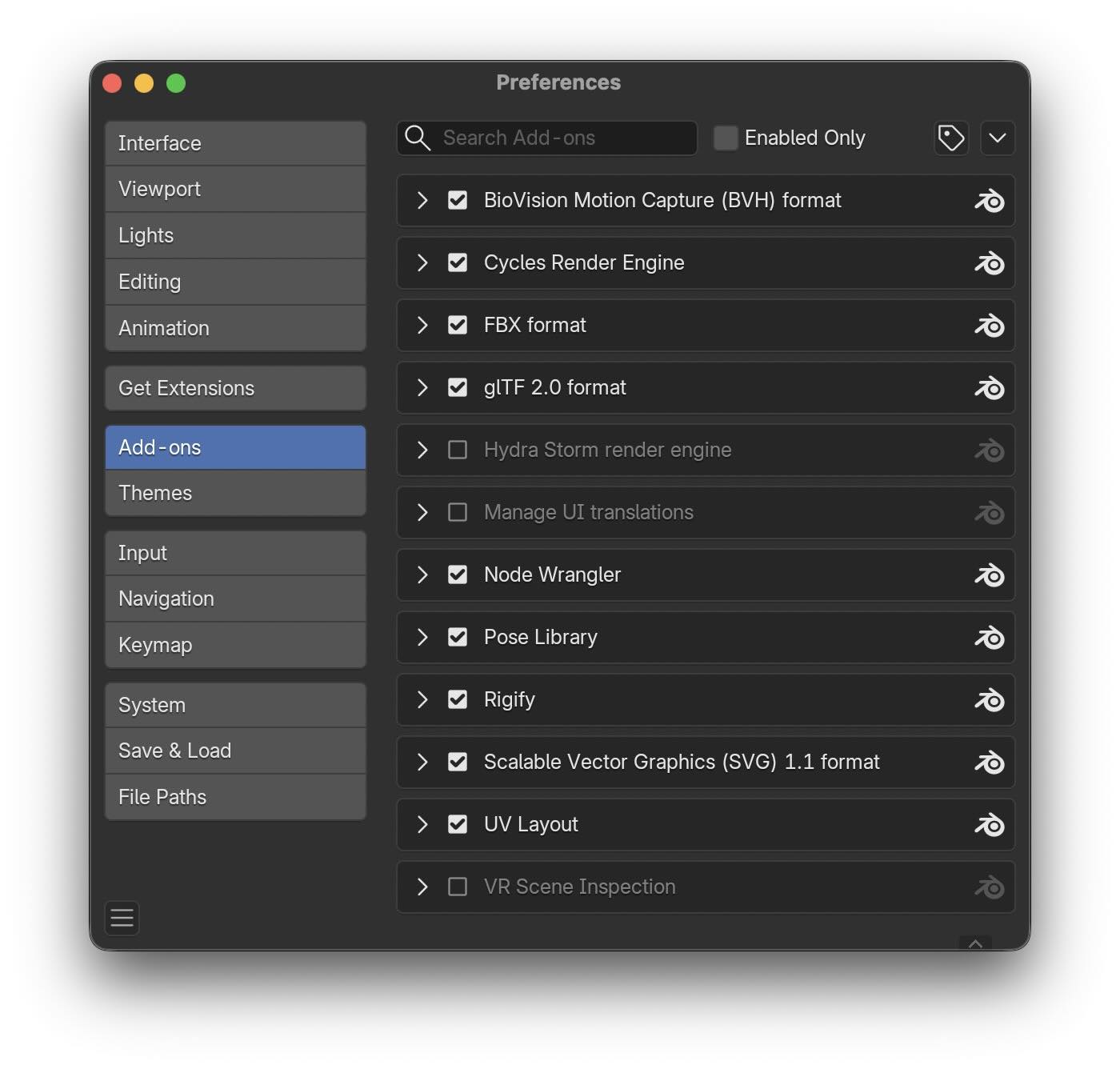
One of the most useful add-on Node Wrangler.
Now you can Ctrl Shift Left Mouse Button on any shading node to see its output in the 3D window.
Node wrangler temporarily routes the output of the selected node, in this example the normal map node,
to a Viewer node,
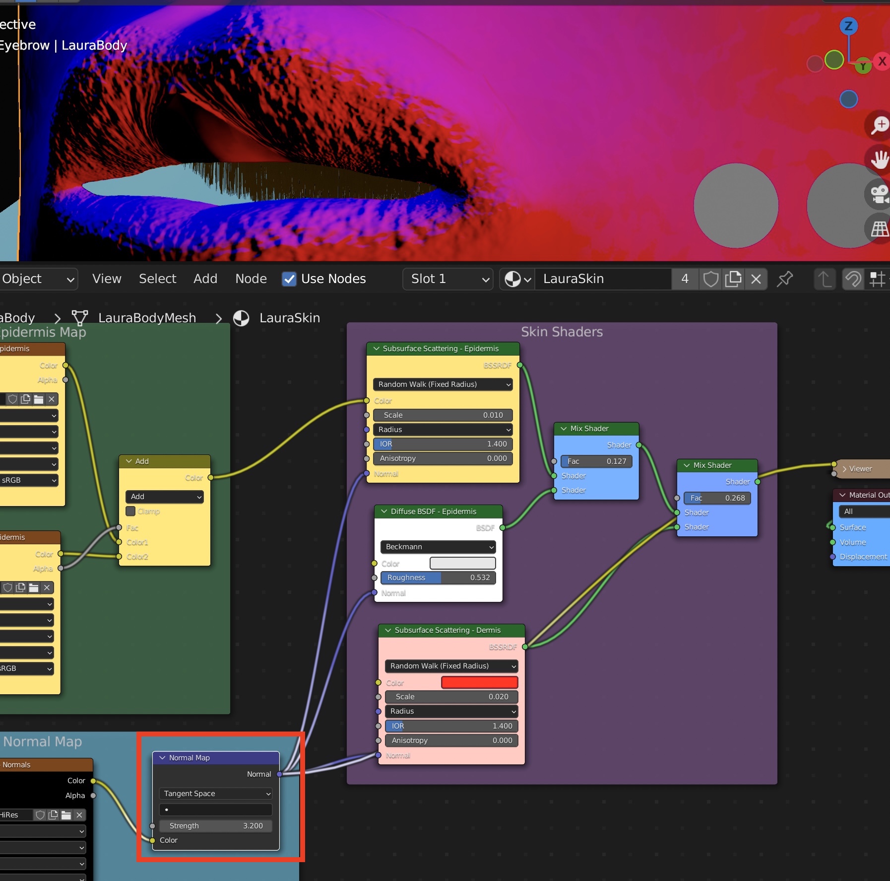 You can click on the final shader node to see the normal output again.
Extensions
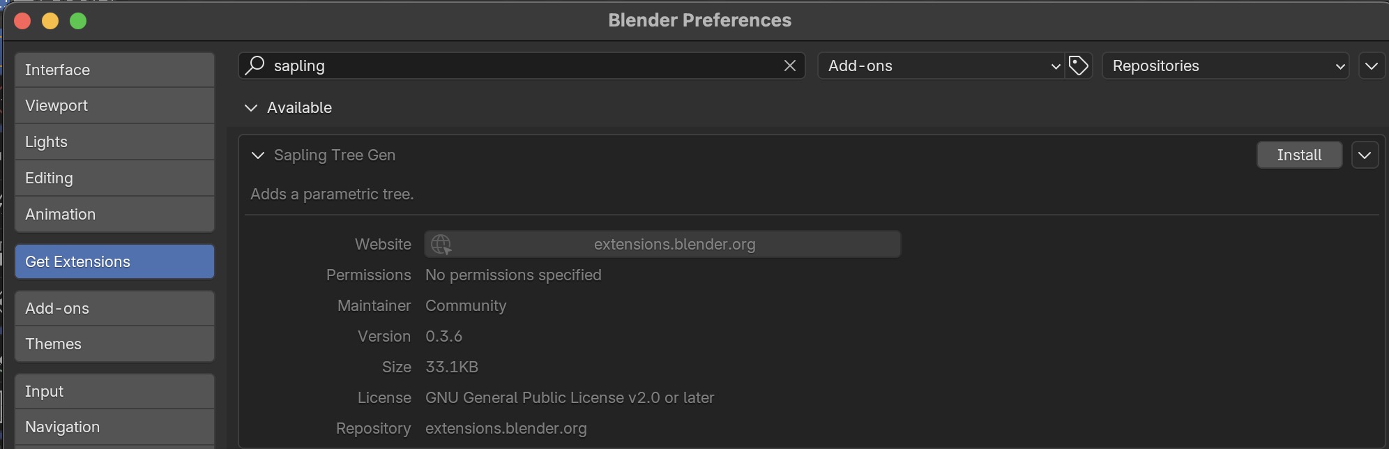
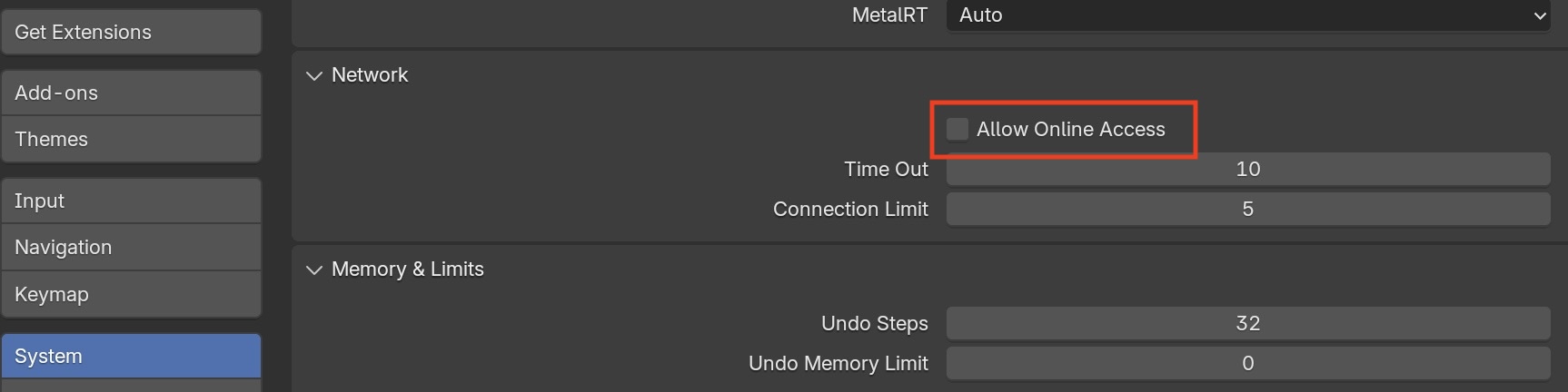
You'll also want several extensions. Go to Edit ➤ Preferences ➤ Get Extensions ➤ Allow Online Access. Now you'll see a list of extensions to install.
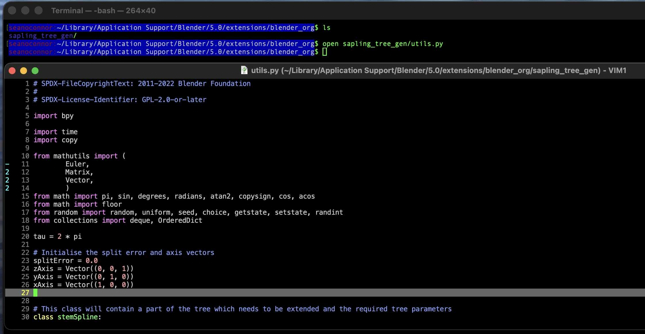
Search for sapling and install the
Sapling Tree Generator Tool
 After doing Install you'll see the local location
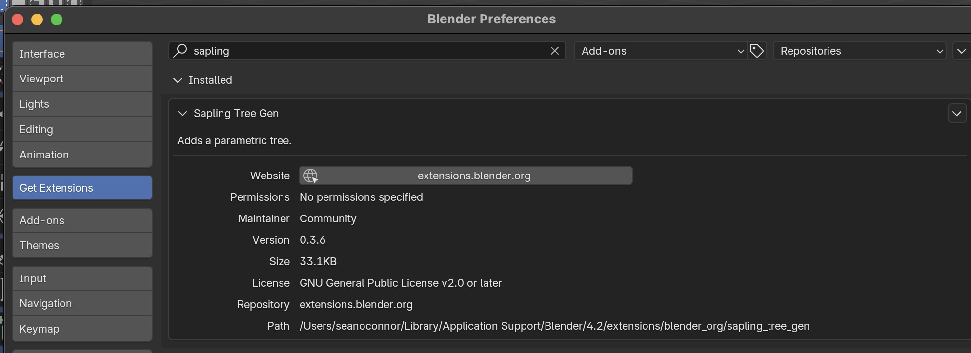
Going to the local location you can see the Python source code which implements Sapling!
Afterwards, turn off internet access again for privacy.
Render Settings for Eevee and Cycles
Cycles Render Settings
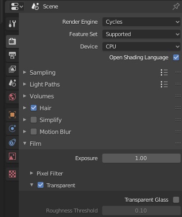
Enable Transparent in the Render options so the world background won't show in the render.
Select the fastest device to use for rendering. This will usually be the GPU.
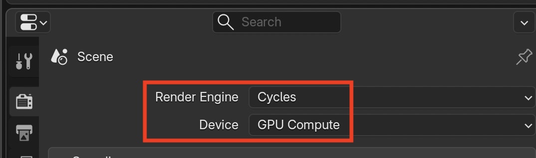
Then, in Edit ➤ Preferences ➤ System ➤ Cycles Render Devices, and
select GPU or CPU. Here is an example of selecting a GPU for cycles rendering on an Ubuntu/Linux PC.
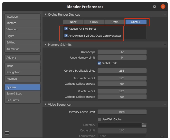
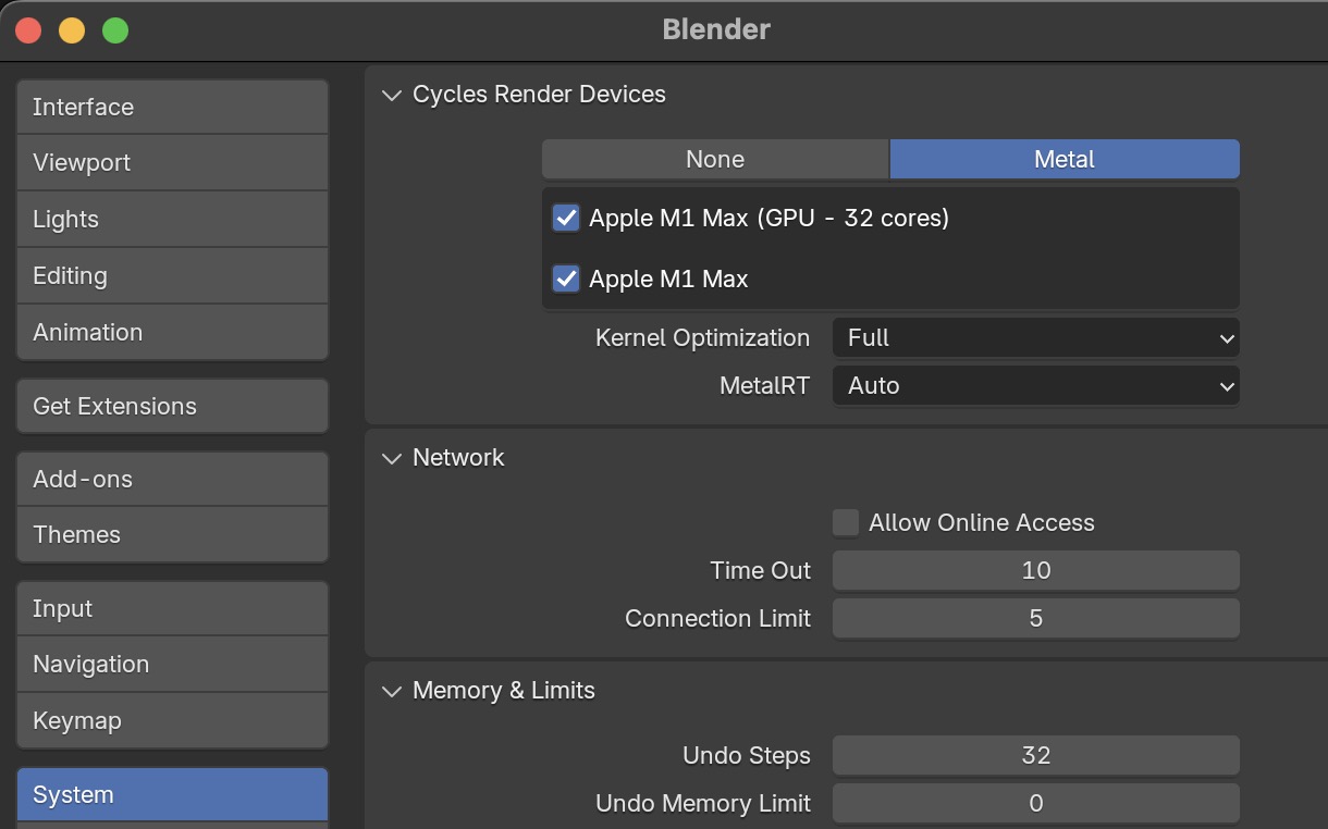
and on the new MacBook Pro with Apple Silicon for both the ARM CPU and M1 Max GPU.
Here are more tips for reducing render times at Blender Guru: 10 Easy Ways to Render Faster in Blender
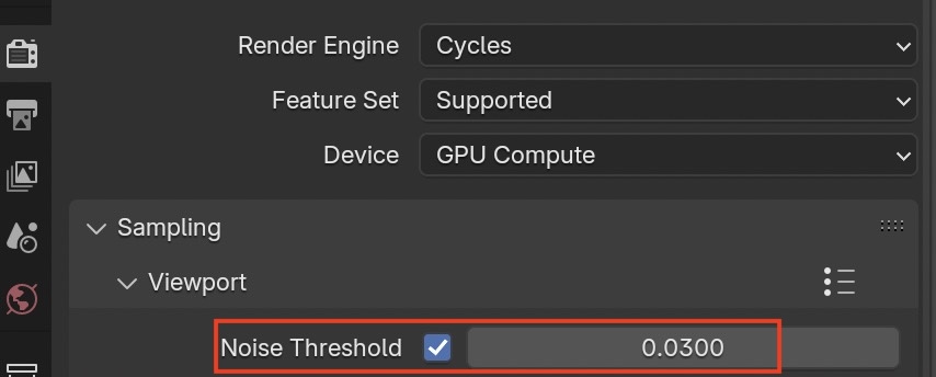
Increase the noise threshold from the default until you notice the render quality start to degrade.
I have a female model with eyes, hair and smooth skin, where noise shows up first.
It's good enough for a render preview, but the final render has more accuracy.
I turn off Denoising since it blurs out the hair way too much.
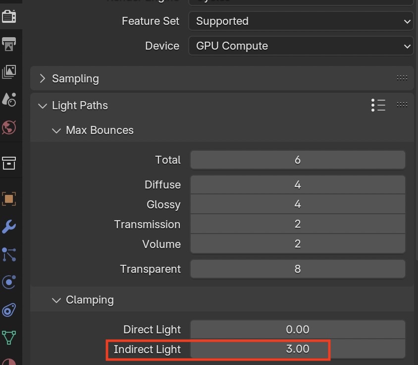
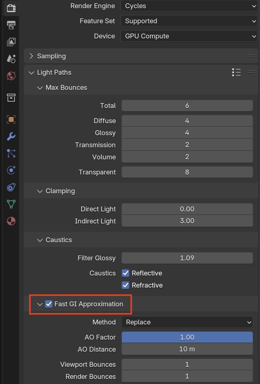
Reduce indirect light clamping. The maximum value for an indirect bounce which is common in transparent materials. Higher values
will be discarded and speed will increase at the cost of render accuracy for caustics.
This setting will subsample your textures and speed up renders if you have very large texture images.
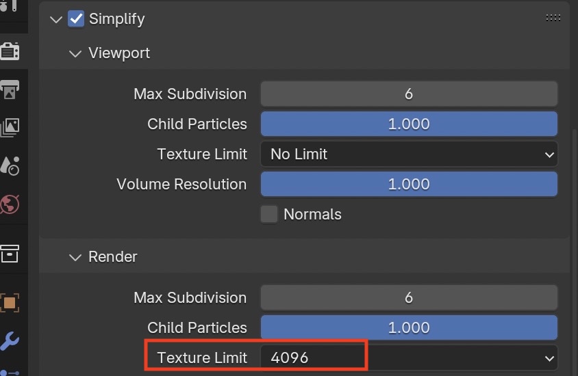
This setting will replace some of the ray tracing with ambient occlusion which is faster but less accurate.
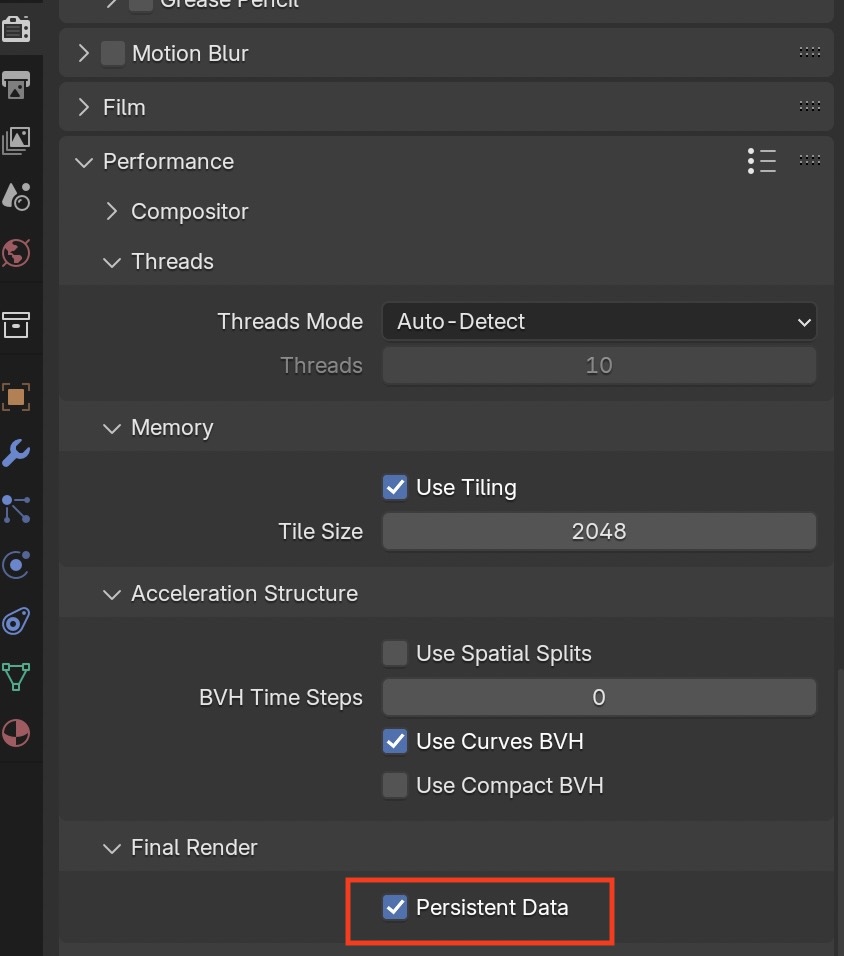
To avoid reloading render settings each time, we can save in memory:
Eeevee Settings
Eevee mode is much faster than Cycles rendering, but not nearly as accurate.
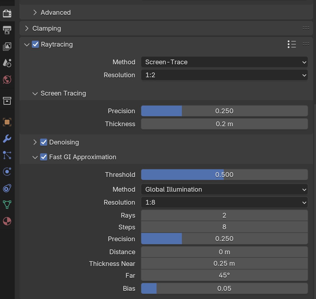
For speed, Eevee doesn't render transparent or reflective objects by default.
So the first thing is to enable ray tracing in Eevee.
 You need to tweak a lot of settings to get renders which are closer to Cycles, refer to
How to user Eevee by Blender Guru
You need to tweak a lot of settings to get renders which are closer to Cycles, refer to
How to user Eevee by Blender Guru
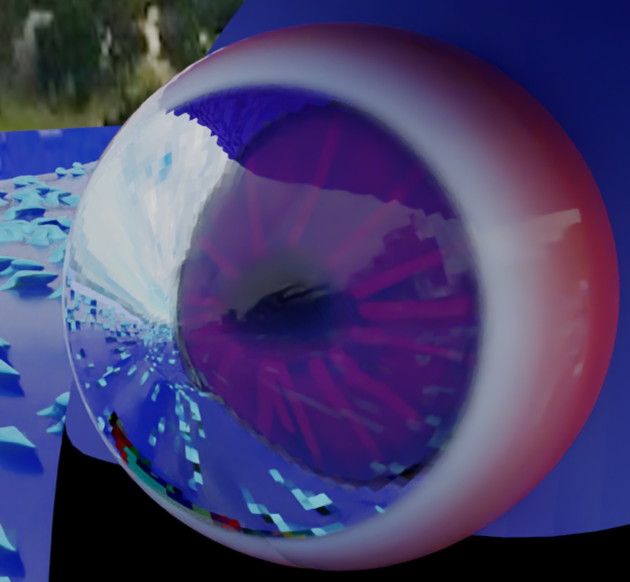
A human eye is a tough case. Let's see how close Eevee is to Cycles:
Eevee render
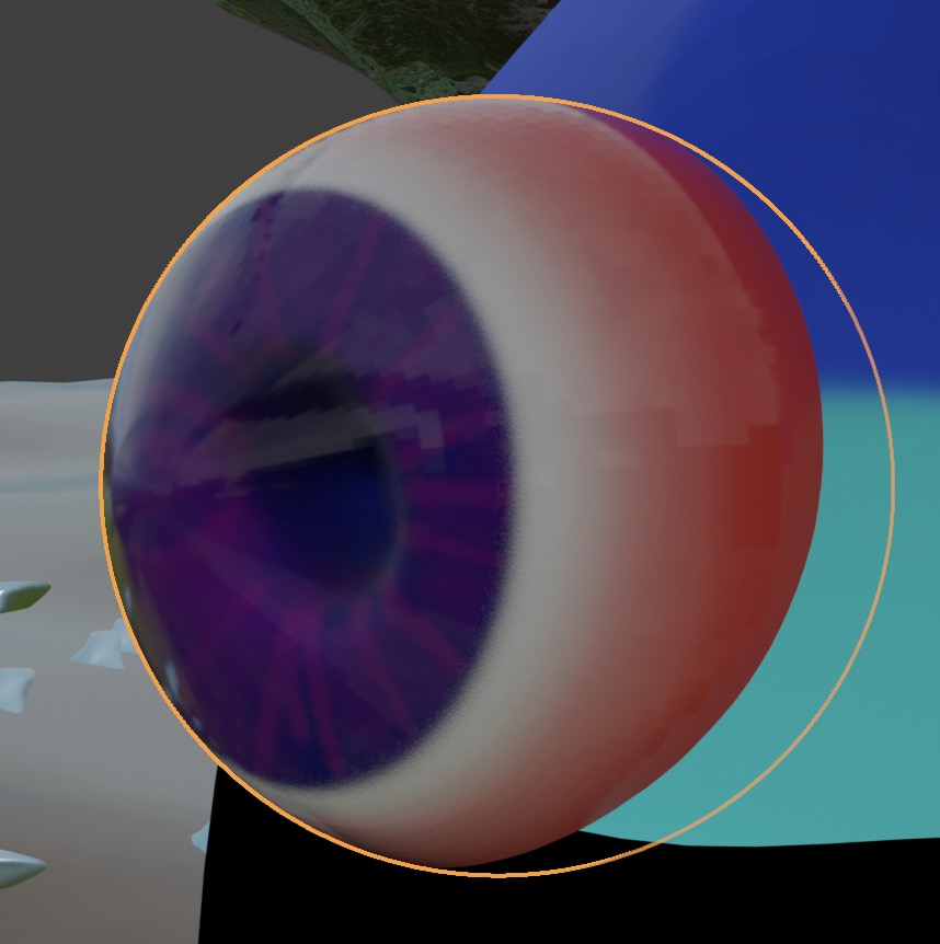 Cycles render
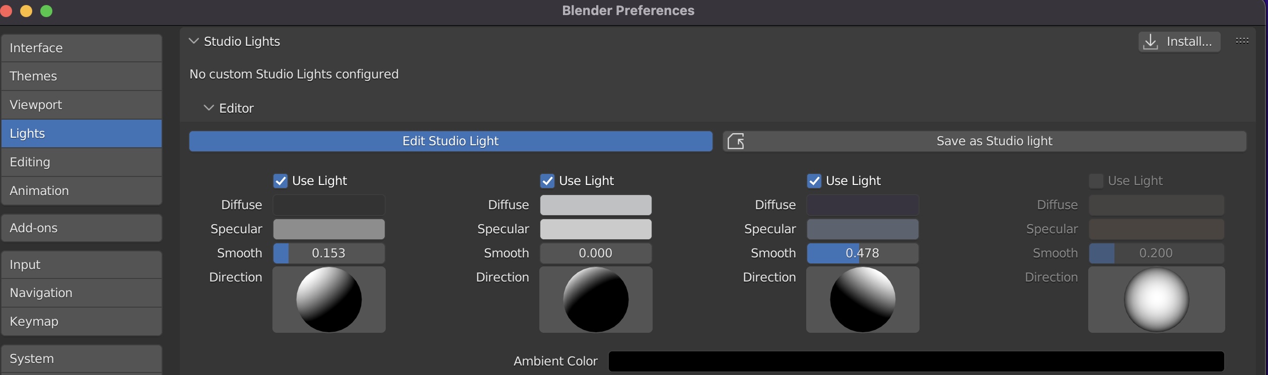
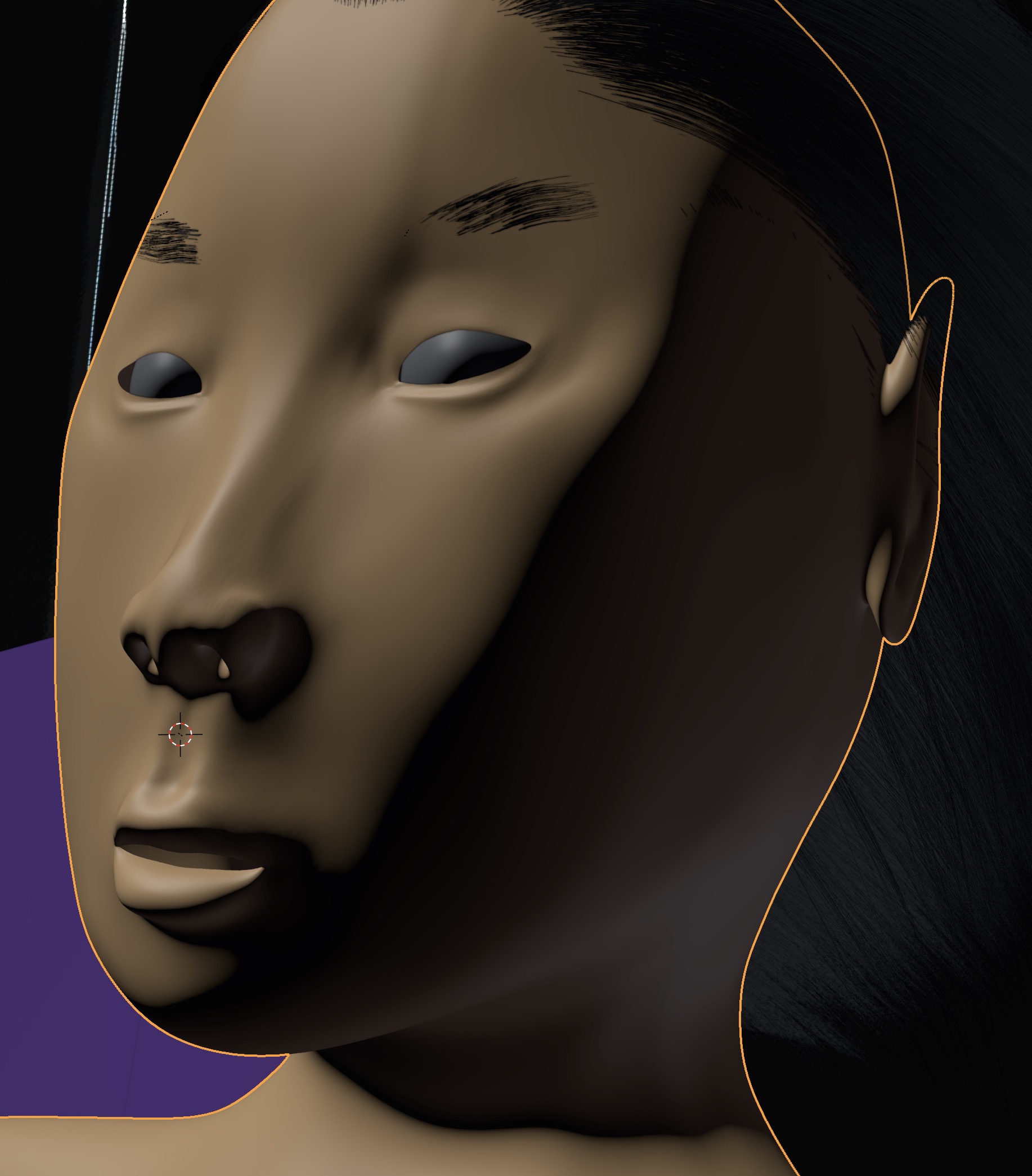
Viewport Studio Lighting
Viewport Shading ➤ Solid Mode
 can be adjusted to give the figure better form definition through shadows when you are modeling.
and it will look like this for a figure,
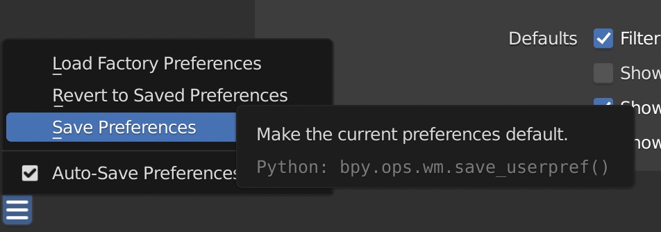
Saving Preferences
When you are all done, save your preferences using
Edit ➤ Preferences ➤ Save and Load ➤ Save Preferences
The user preferences files are saved in on macOS in $HOME/Library/Application Support/Blender/blender version/config and in Linux at $HOME/.config/blender/blender version You can freely copy these settings files back and forth between macOS and Ubuntu Linux systems. The same goes for the *.blend files.
Importing from Blend File
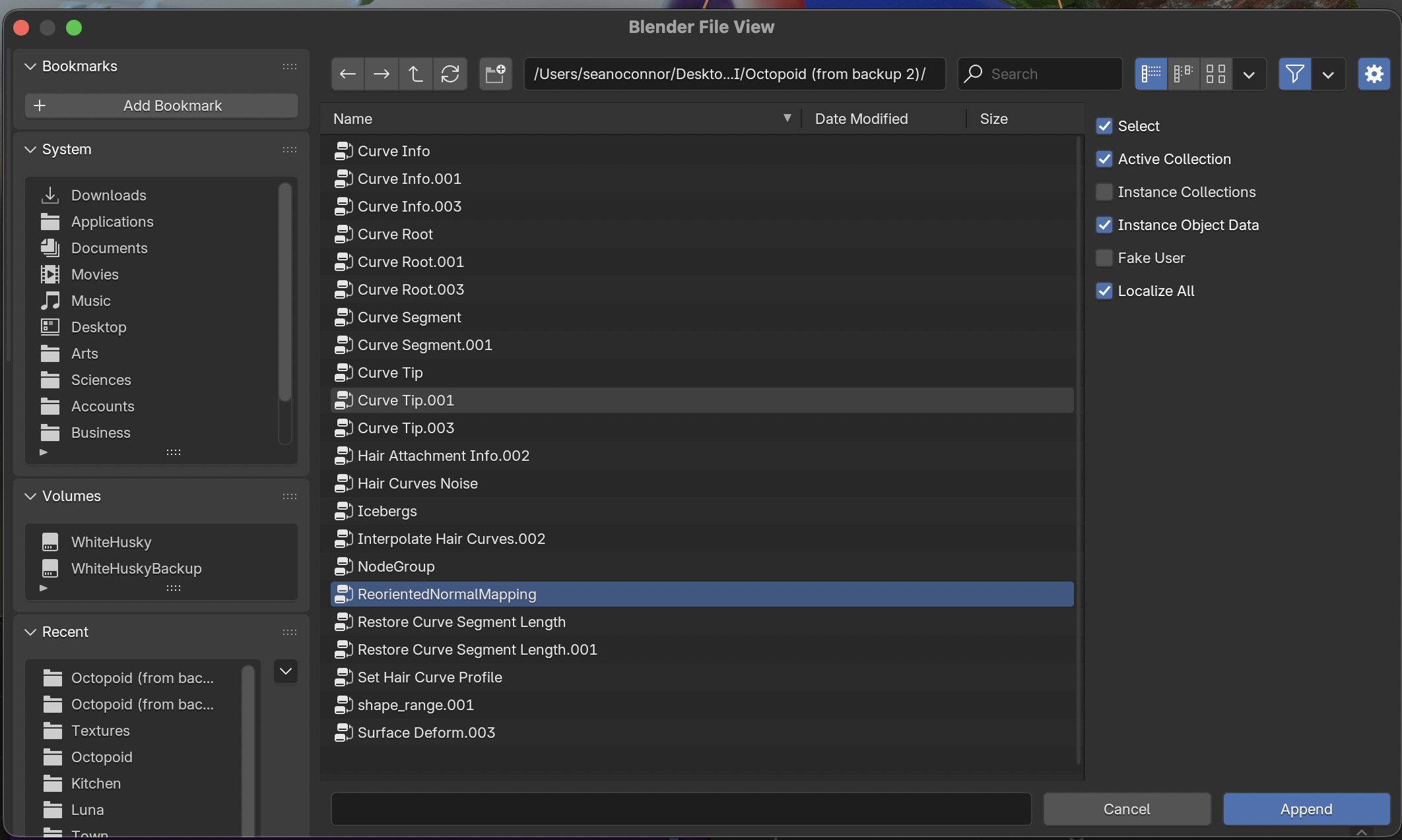
You can import objects from a different .blend file. Here's an example of importing a user defined node group.
File ➤ Append Go through the directories and select the .blend file.
In the Blend File View, go into the Node Tree folder and select the
ReorientedNormalMapping group, and hit Append
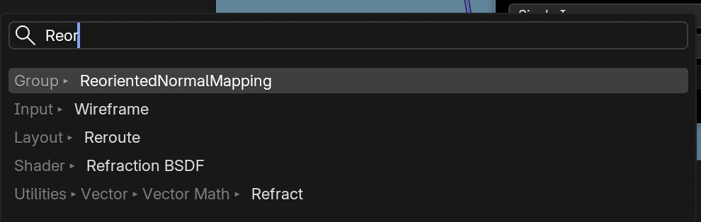
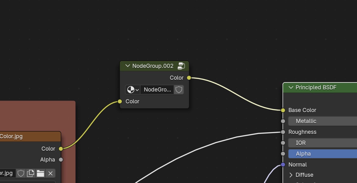
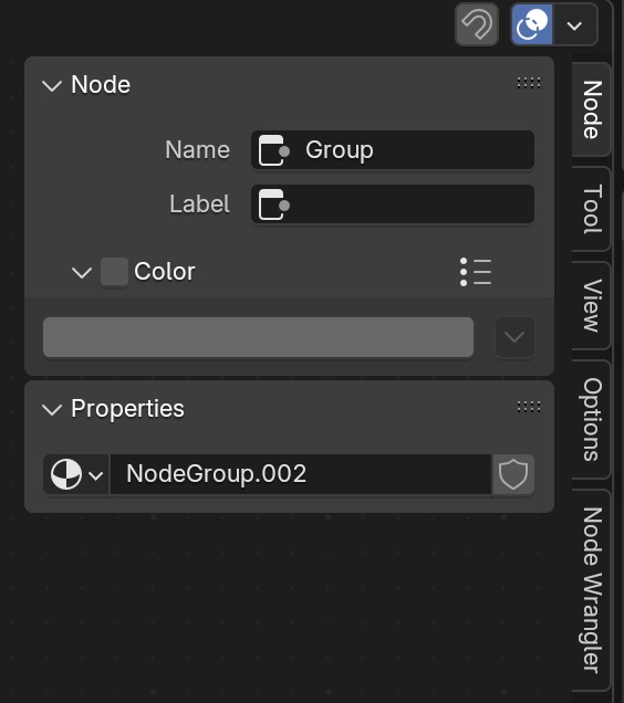
Now it is copied into the current Blender project. You can search for it when adding a new node:
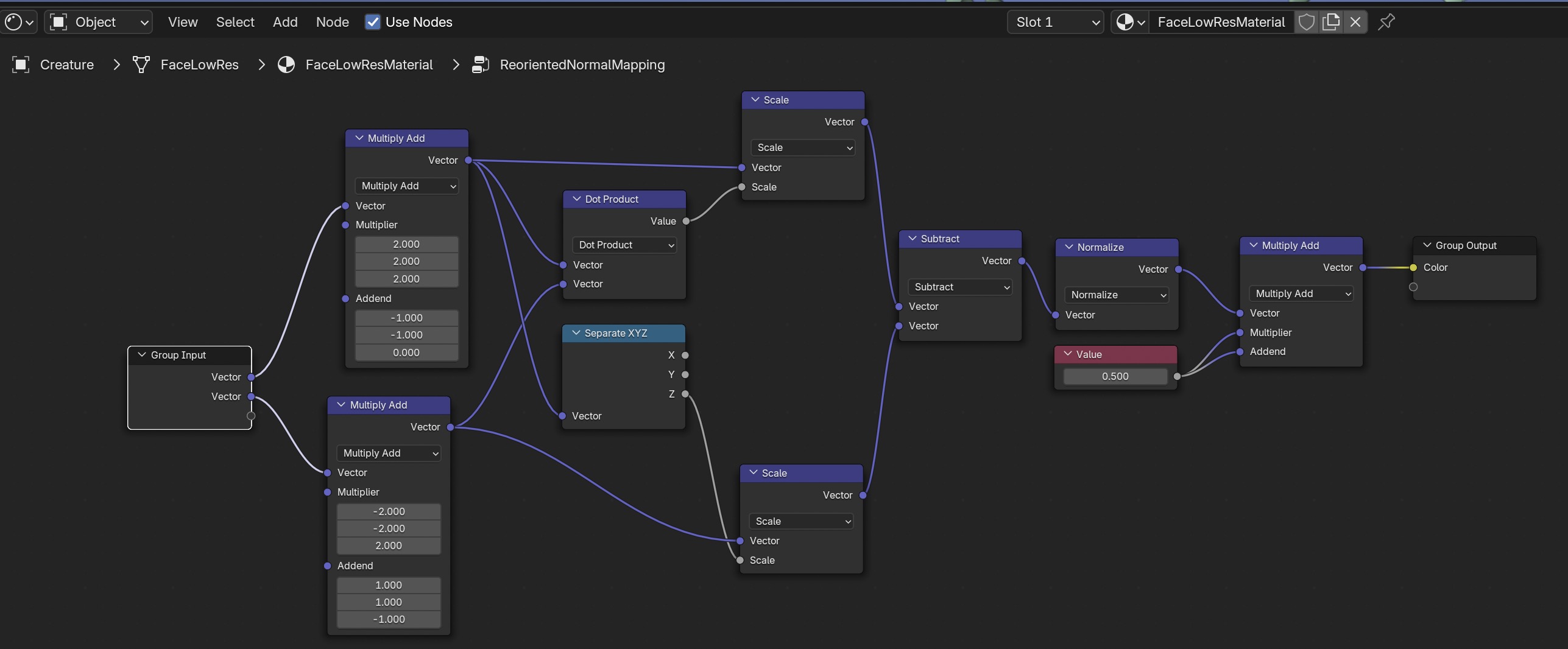
 and here is the node and what's inside it,

Programming
Blender has a graphical programming language. You can group sets of nodes into frames. Or you can go further and create a group of nodes with labelled inputs and outputs which act like a function.
Frames
You can group a collection of nodes into frames by
Selecting them with the mouse then doing Shift P
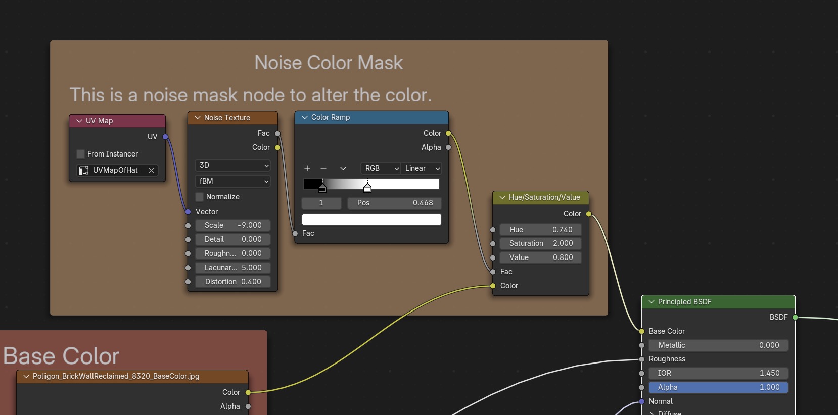
N will show the frame properties.
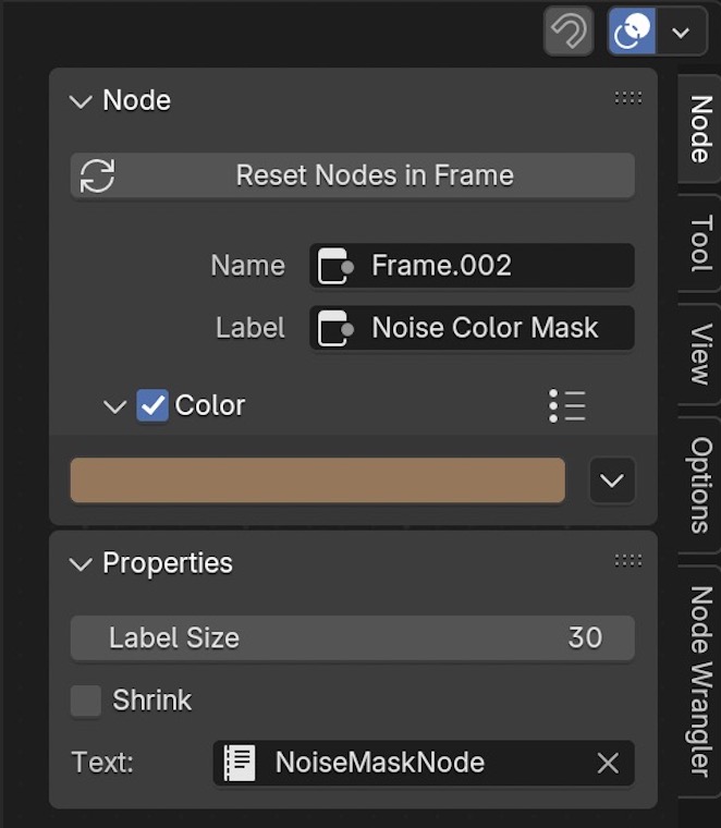 Change the Label of the frame to Nois Color Mask
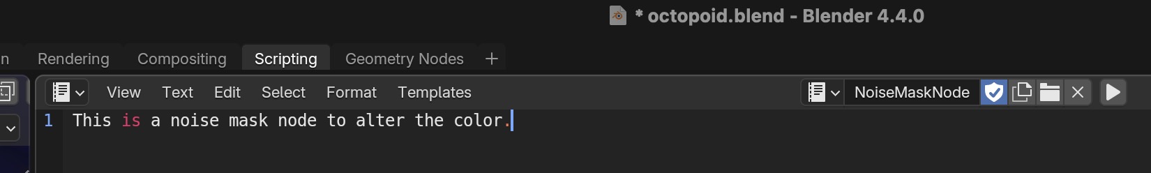
Then add documentation which shows up beneath the label as follows:
Create a new file in the Scripting Tab, edit it, name it and save it under NoiseMaskNode.
Then select this name in the node in the Text: field.
Change the Label of the frame to Nois Color Mask
Then add documentation which shows up beneath the label as follows:
Create a new file in the Scripting Tab, edit it, name it and save it under NoiseMaskNode.
Then select this name in the node in the Text: field.
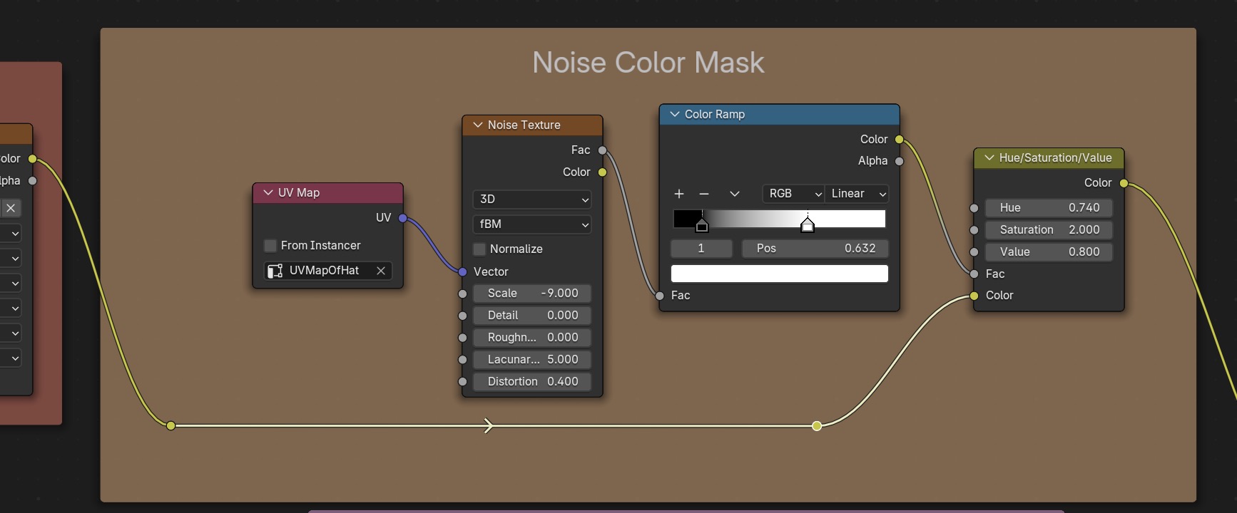
To make it easier to see connections between nodes, you can add connection to the link between two nodes, by
doing Shift Right Mouse Button and moving the cursor across the link.
Then use G to move the connection around.
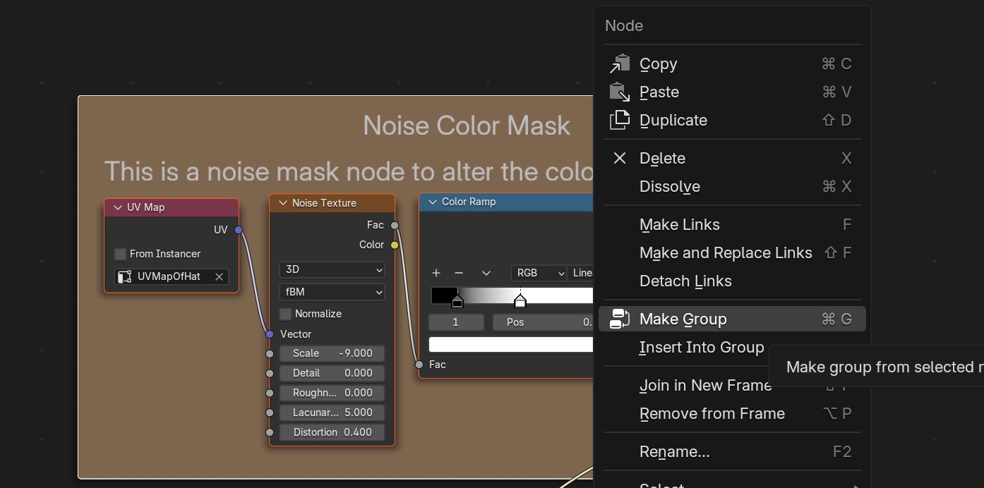
Groups
You can go further than frames: you can select any nodes and create a group with input and output parameters which
acts like a function.
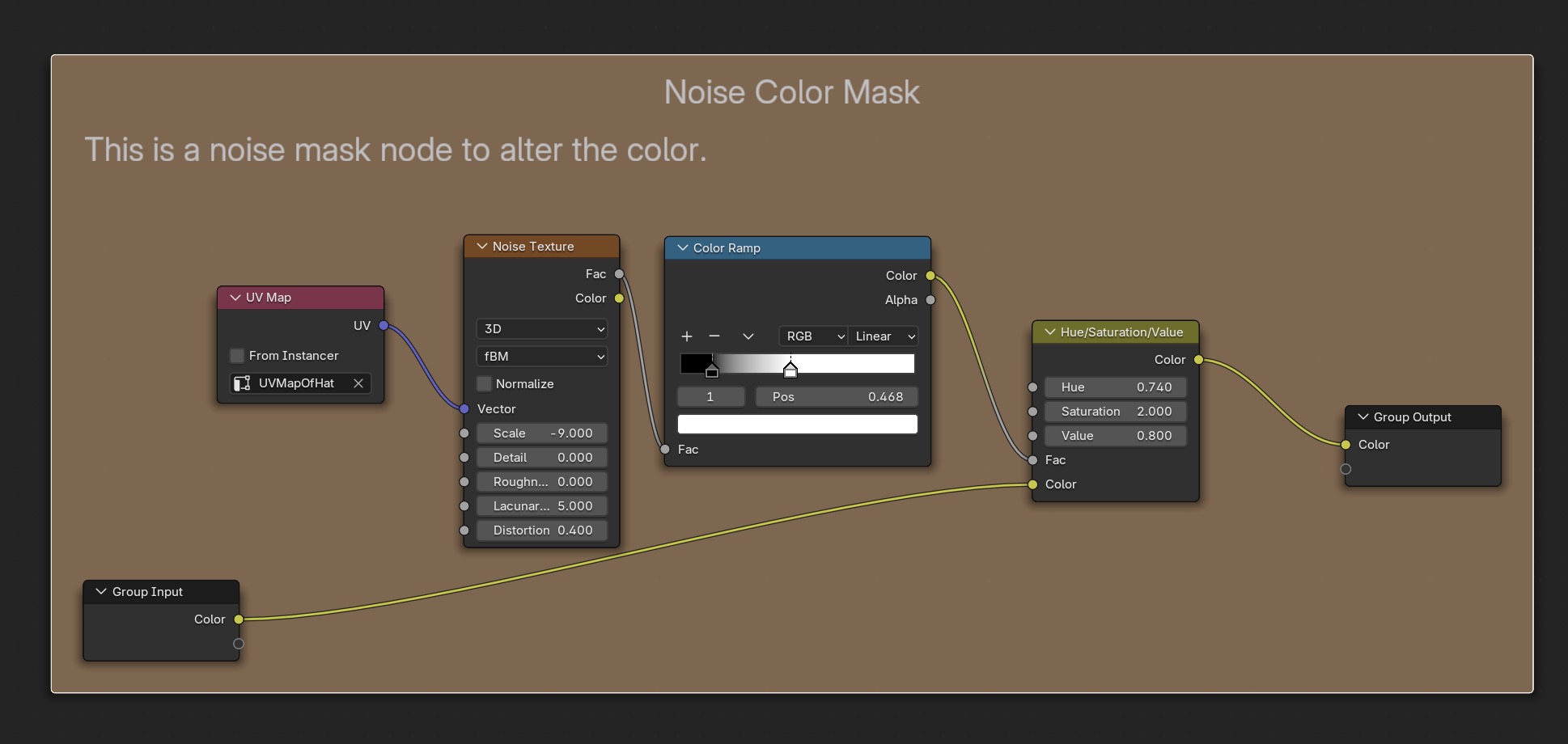 Hit TAB to zoom out to see the new group:
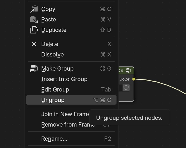
You can also revert back to a frame from a group with Ungroup
User Interface
You'll need to memorize a number of Blender hotkeys.
3D View Hotkeys
| Hot Key | Action |
|---|---|
| Shift RMB | Position 3D cursor. |
| ~ 3 | Center object in view |
| Ctrl Tab NUMBER | Select the mode: object, edit, sculpt, weight paint, texture paint, vertex paint, particle edit. |
| Tab | Toggle between object and edit modes |
| z NUMBER | Select wireframe, solid, material preview (Eevee), render |
| G | Move object: G for grab. G follwed by SHIFT scales down the motion to fine tune the position. |
| Shift D | Duplicate the node, ALT D creates an instance (shares the original mesh and materials, but independent location, scale, rotation) |
Shader Hotkeys
| Hot Key | Action |
|---|---|
| Select the node with the mouse, then M | Mute the node: toggle it on and off. |
| Click on the shader node Ctrl Shift Left Mouse Button | Object shows shading from the selected node only. To turn off, Ctrl Shift Left Mouse Button on last shader node connected to the material output. |
Object Coordinates Tip
Following Blender Guru's recommendations I always make sure an object's scale is set to 1 and the rotations are zero
Ctrl A ➤ Apply Rotation and Scale
as shown in the properties window toggled by N.
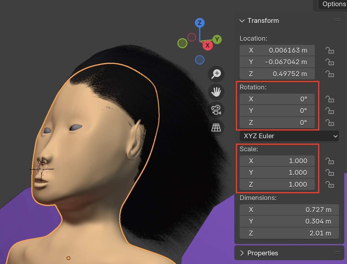
I also set the object origin to the center of mass. This makes translating and scaling the object size much easier. Select the object, then Right Mouse Click ➤ Set Origin ➤ Origin to Center of Mass (Surface) But set the origin differently if you use a mirror modifier on the object. The origin shows up as a yellow dot within the object.
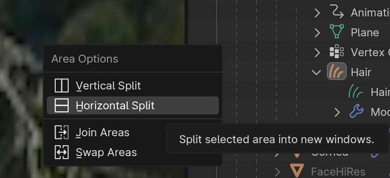
Manipulating Windows
To create a new window, or join windows, right click mouse with the cursor hovering over
the boundary between two windows to get a menu.
Lighting
I'll talk about lighting for outdoor scenes. We'll need both light from the sun and from the environment (sky and ground). A scene with a simulated ocean is a tough case which won't look right at all unless you have environment lighting enabled and use a sky scene. In the next sections, we'll show environment lighting by itself, then sunlight by itself, and finally combined sun + environment lighting. For an introduction to lighting refer to Fundamentals of Lighting in Blender by Blender Guru
Environment Lighting
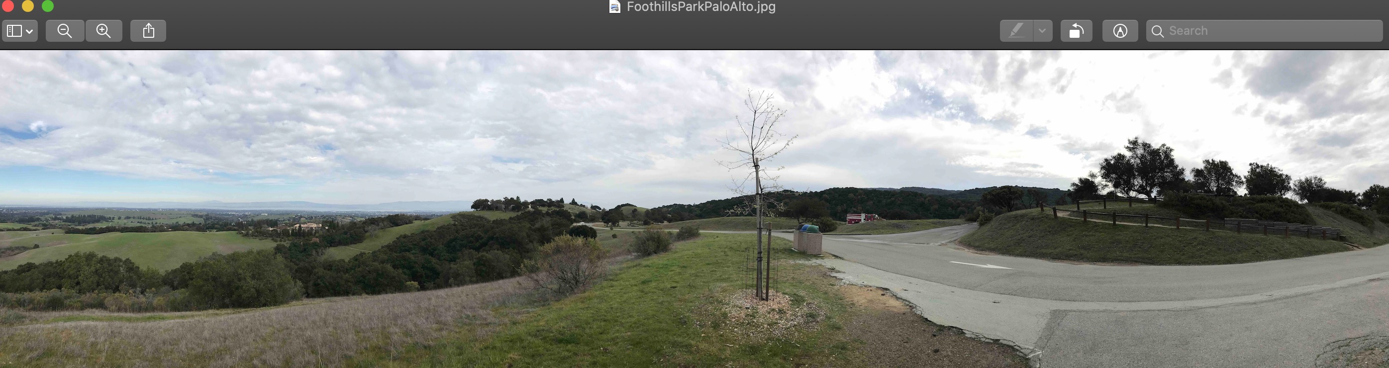
Environment lighting comes from a panoramic image with a high dynamic range (HDR). I took an HDR Pano image with an iPhone 7+ camera of an outdoor scene at Palo Alto Foothills park.
If Blender is spending a lot of time Updating Lights whenever you switch between Evee and
Cycles, you can increase the speed by scaling down the image width and height at the cost of detail using
Gimp.
Go to the Shader Editor Workspace. In the Shader Data select
World instead of object and use Shift A to add these nodes.
The first is an Environment Texture
node. We open the HDR image file in the node, and the name changes to the file name.
Ideally you will use an image which is close to the background of your scene, to get the proper color of lighing,
e.g. blue sky and ocean if you are modeling a sailing ship.
Add a Hue Saturation Value node for minor tweaks to the image colors and brightness.
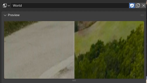
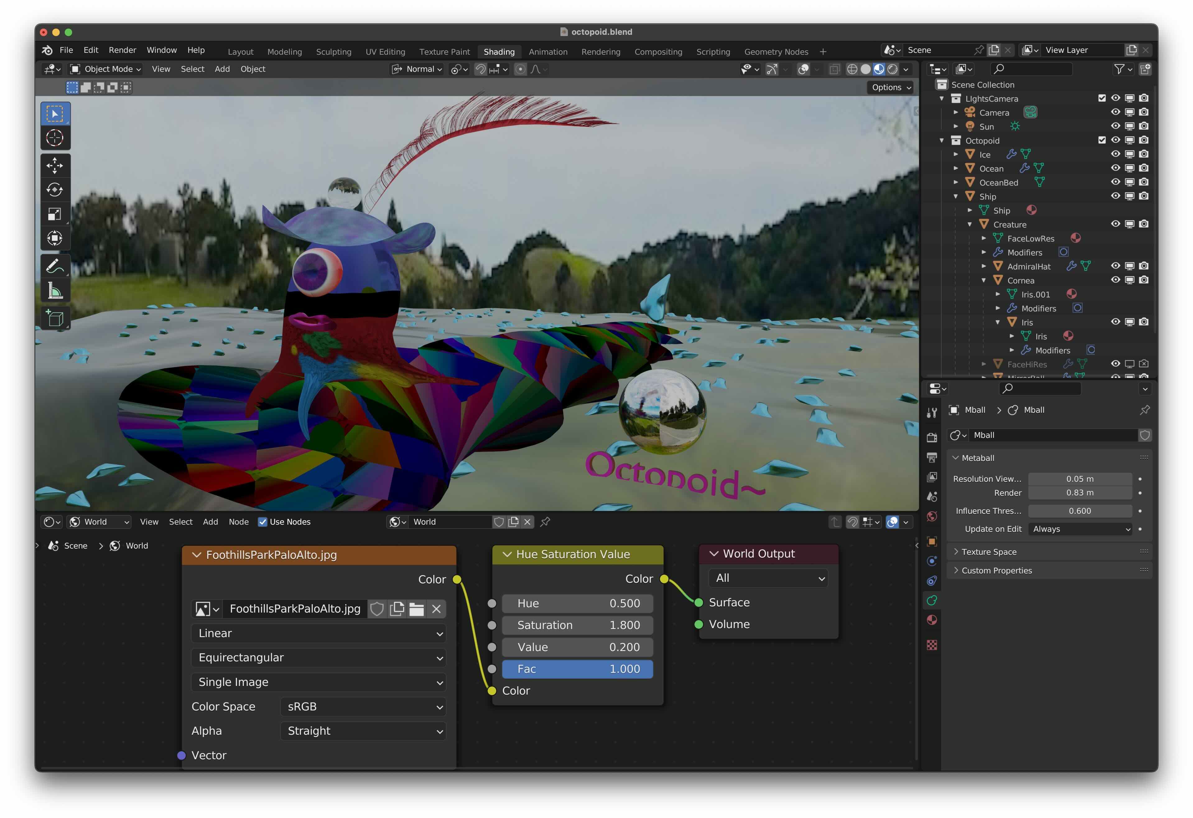 You can see the color and brightness changes in the preview panel, and in the lighting of your scene itself, of course.
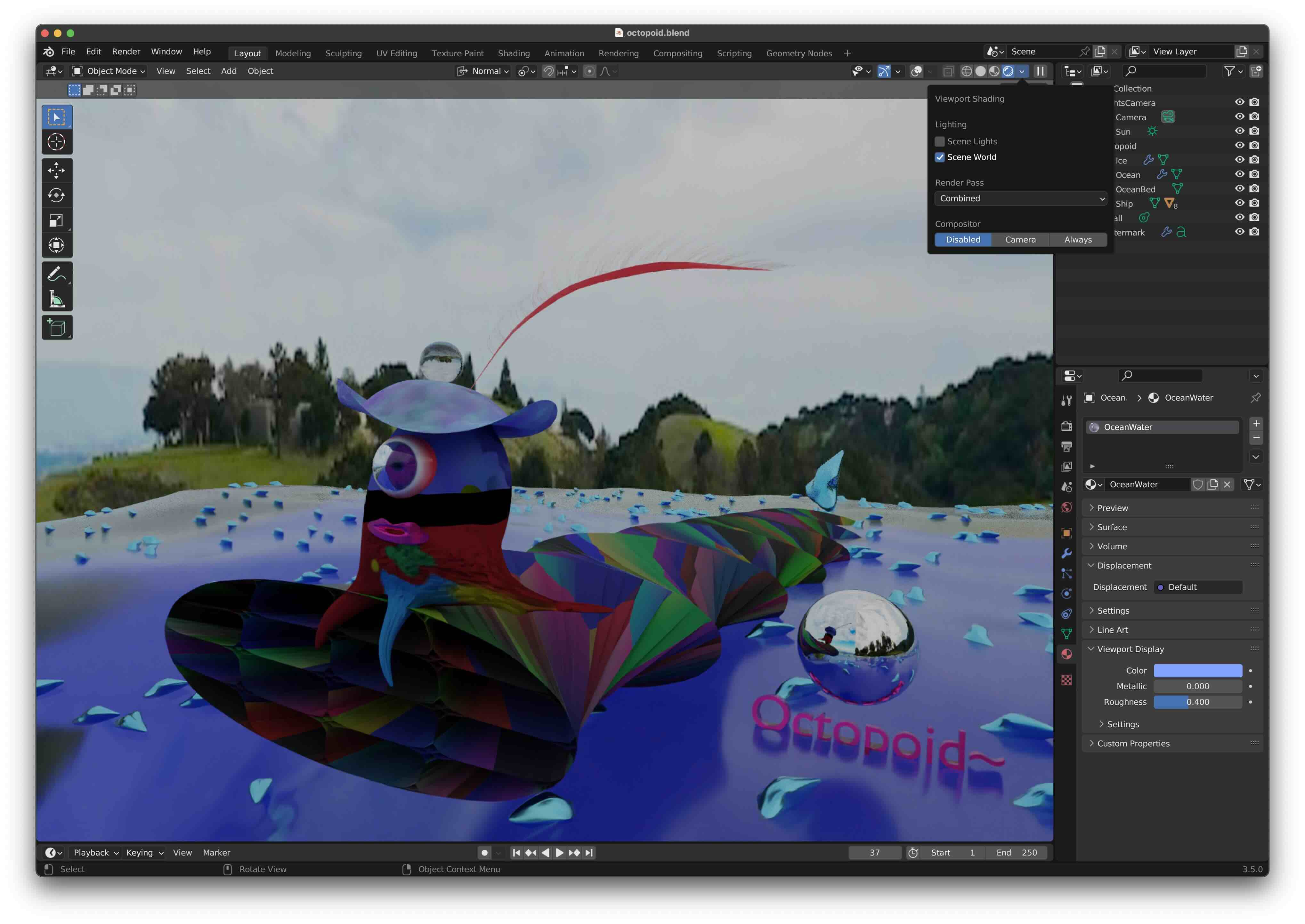
To show only the environment lighting, in the 3D viewport, select
Viewport Shading ➤ Scene World.
but deselect Viewport Shading ➤ Scene Lights.
Here is the Cycles render:
Sunlight
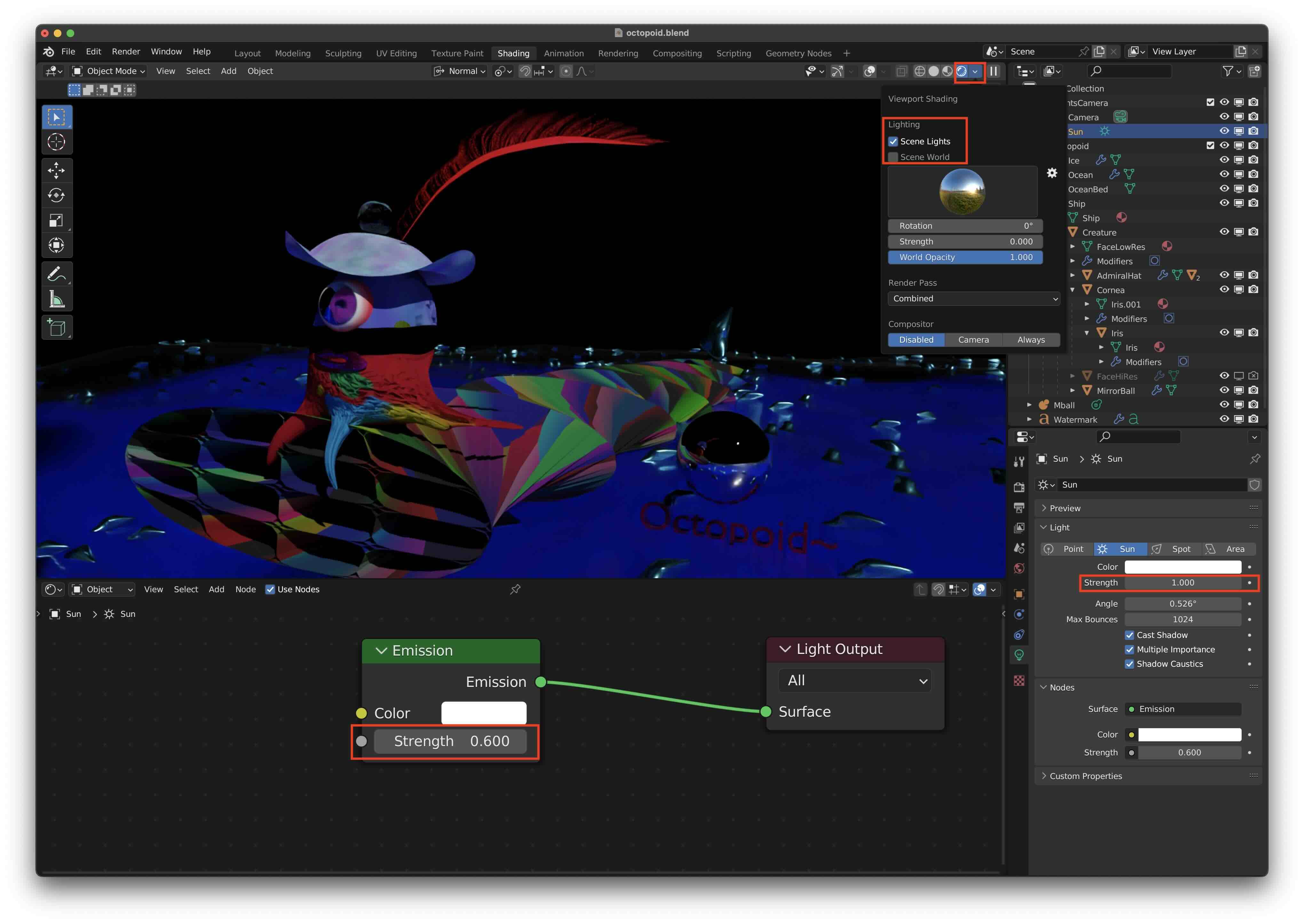
For sunlight, only the angle, not the position matters. Adjust the angle of the sun relative to the objects. Enable multiple importance sampling to reduce noise.
To see the sun lighting only, in the 3D viewport, select Viewport Shading ➤ Scene Lights. but deselect Viewport Shading ➤ Scene World.
When rendering with evee, only the sun strength in the panel changes the sun intensity;
the emission node values don't seem to have any effect.
When rendering with Cycles, both the sun strength and the emission node strength matter. I usually keep the sun
strength = 1 and adjust the emission strength.
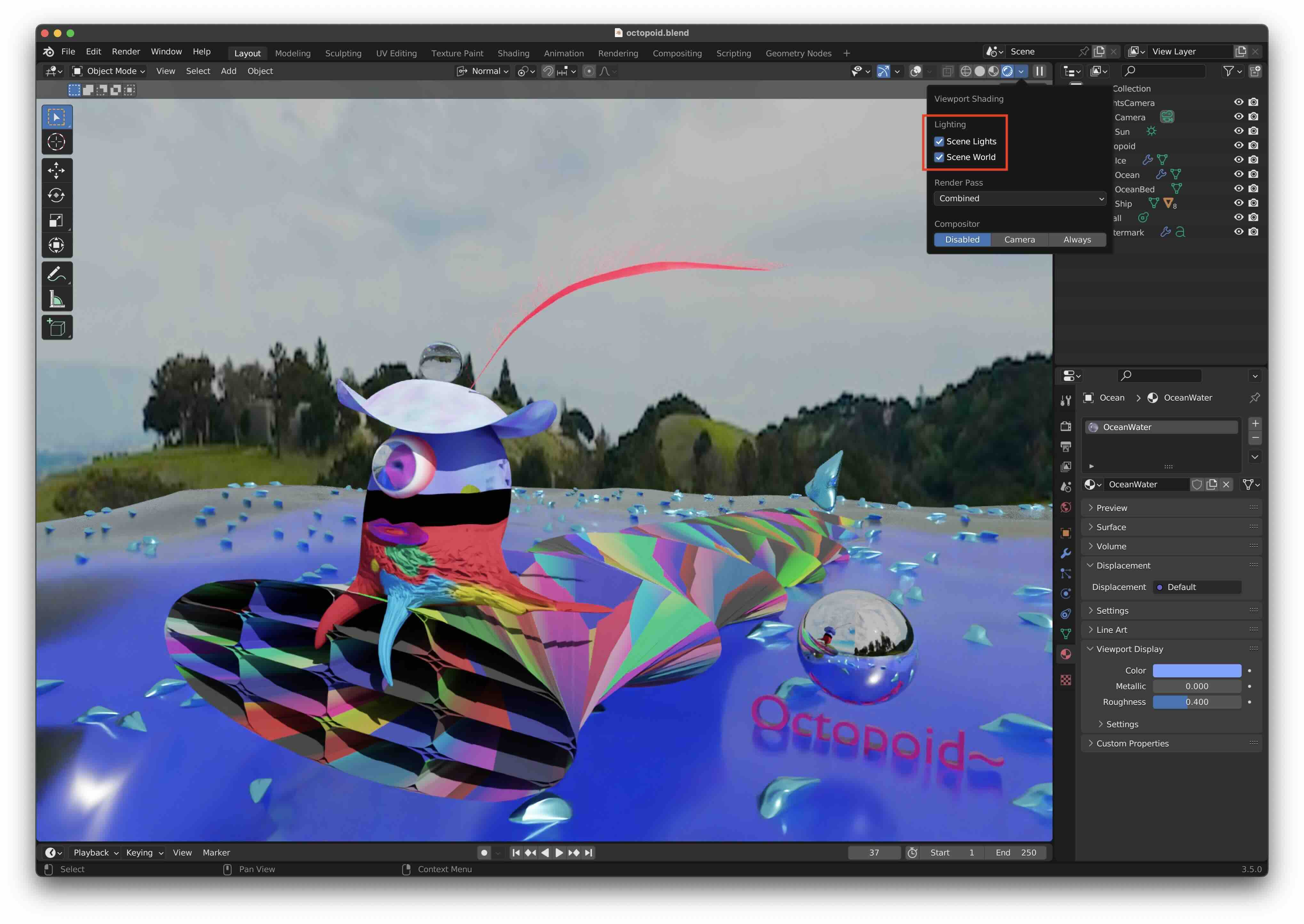
Combined Lighting
To see the combined lighting in Cycles render, select both
Viewport Shading ➤ Scene Lights and
Viewport Shading ➤ Scene World.
Camera
Settings
The 50mm focal length is similar to how the human eye sees. 35mm has a slightly wider angle field of view, wider depth of field and less bokeh.
Clipping
Objects are clipped in the 3D view by default when they are closer to the camera than 1 meter, which is too large. Change this to something small using N ➤ View Tab ➤ Clip Start type in 1cm You'll need to do this in every workspace!
You may still have clipping in the camera view for objects which are far away. To fix this, increase the clipping end distance in the camera settings using
Outliner Panel ➤ Lens ➤ Clip End
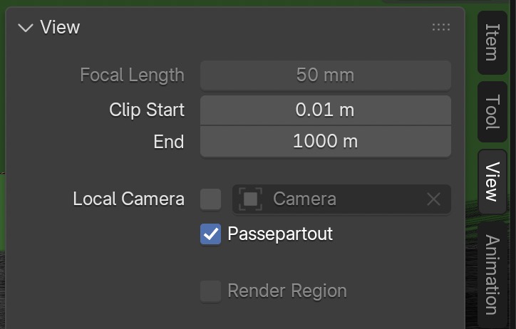 For clip start, I've used a tiny distance 1 cm and for clip end, a really large distance 1 km
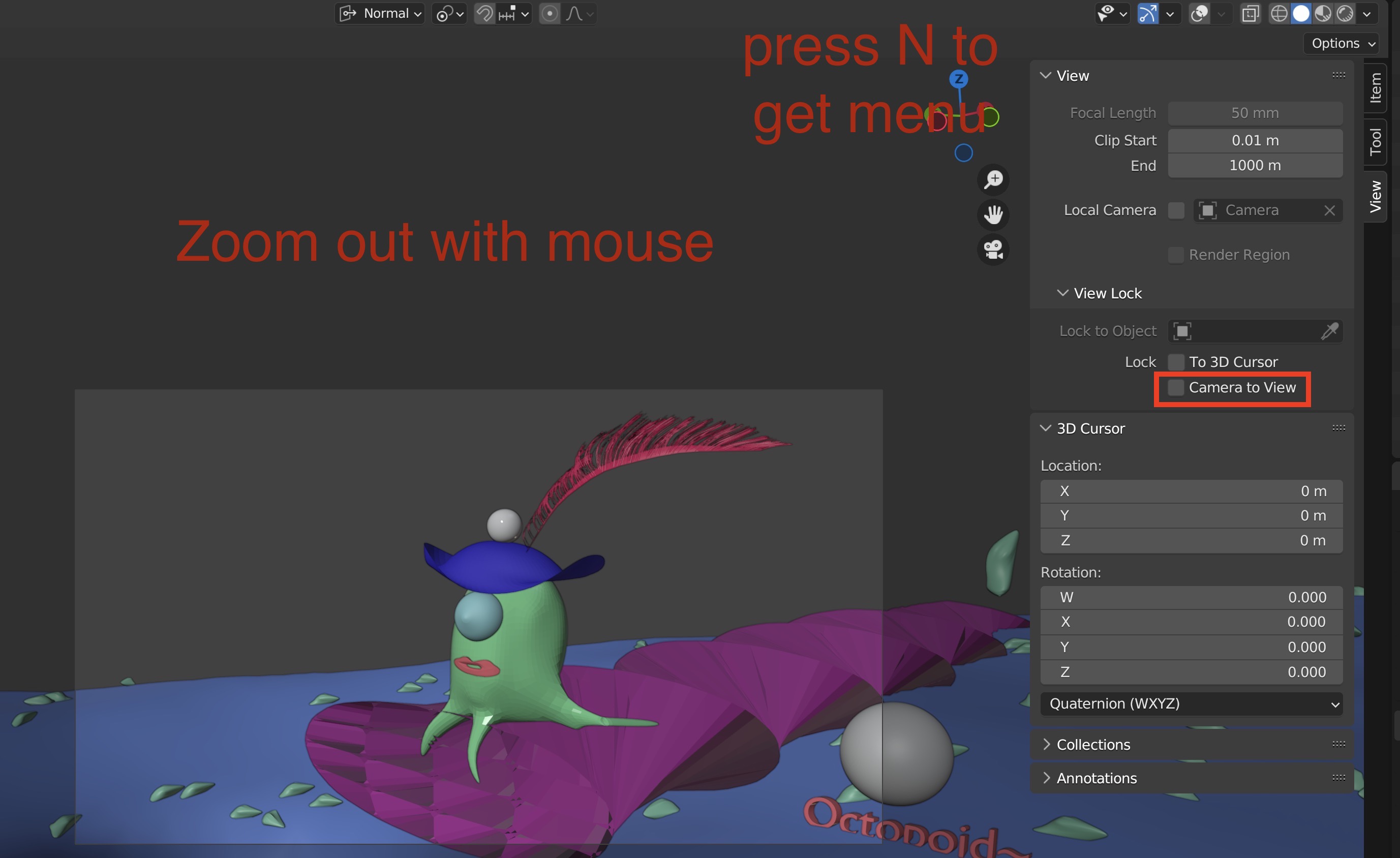
Locking the Camera to the View
By default, when you are in camera mode, moving the viewpoint dumps you out of it. Stop that by setting N ➤ View ➤ View Lock ➤ Lock ➤ Camera to View You'll need to do this in every workspace!
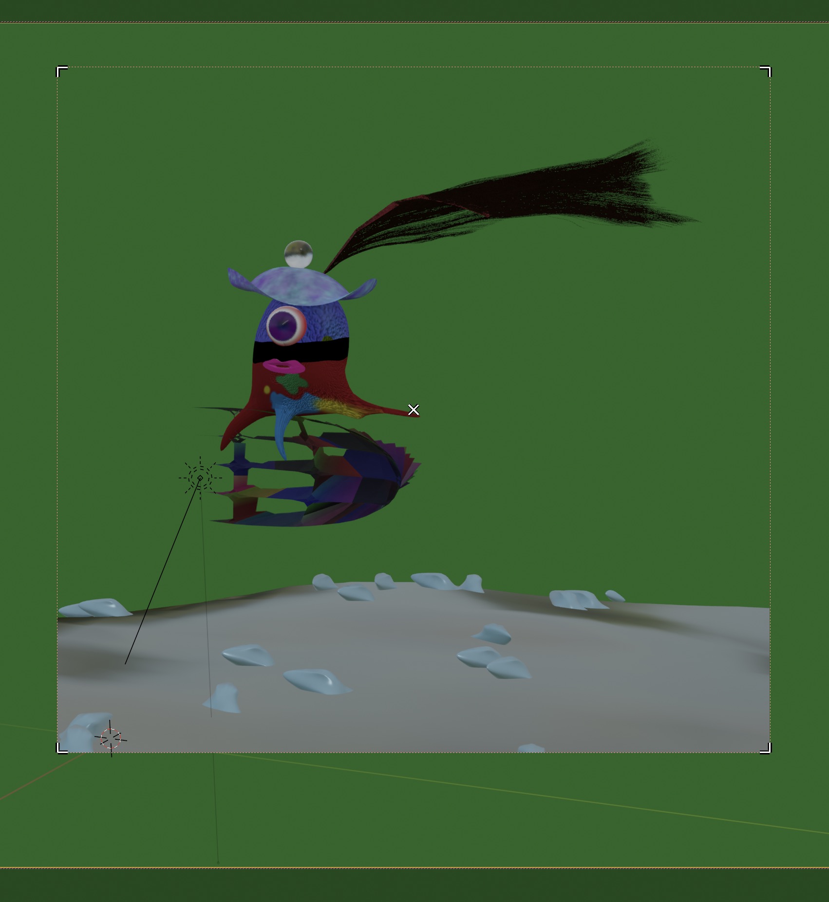
Enlarging the Camera View
To enlarge the camera view to fit the entire 3D window, go into camera mode with 0, then select
View ➤ Cameras ➤ Frame Camera Bounds
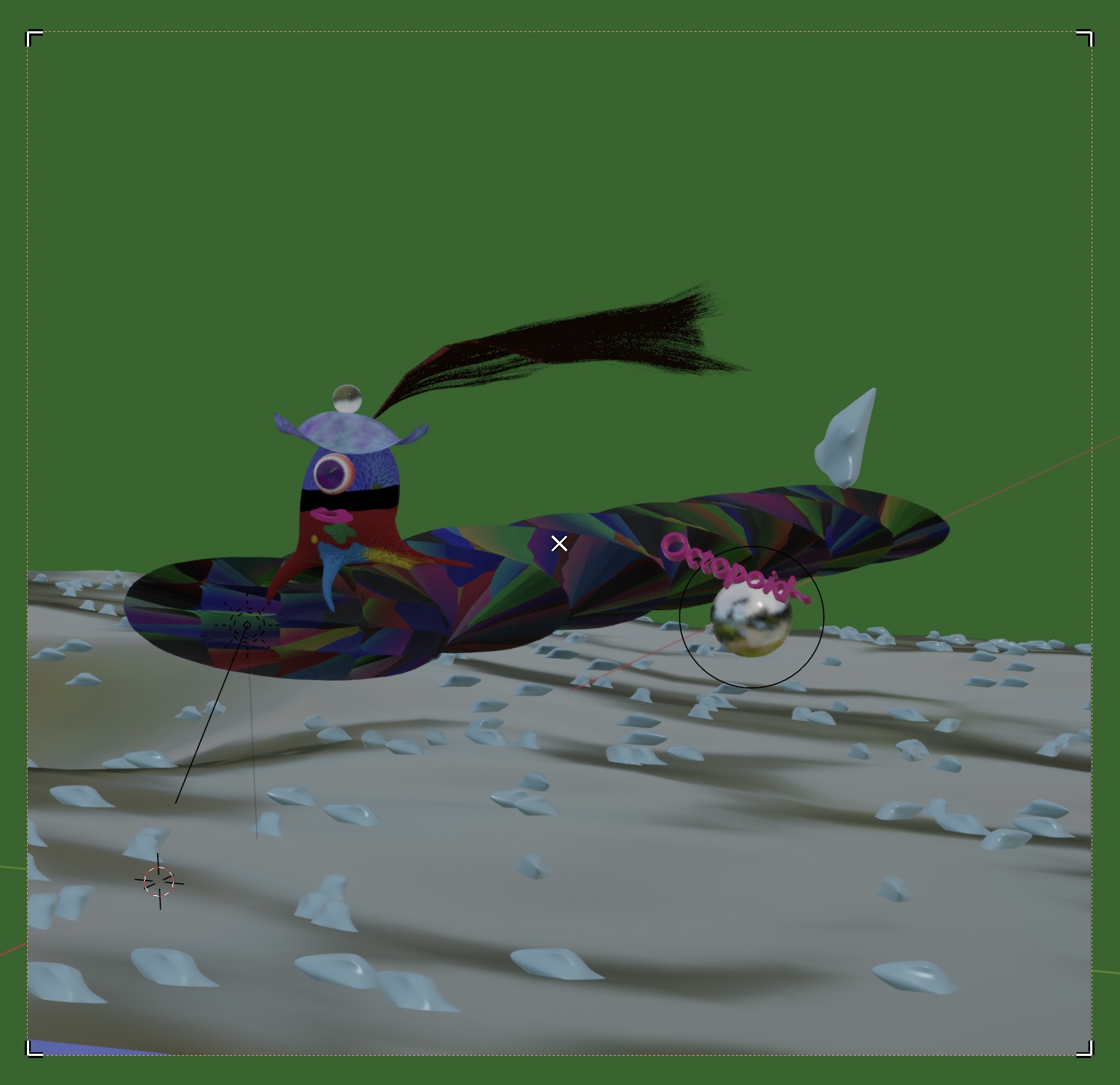
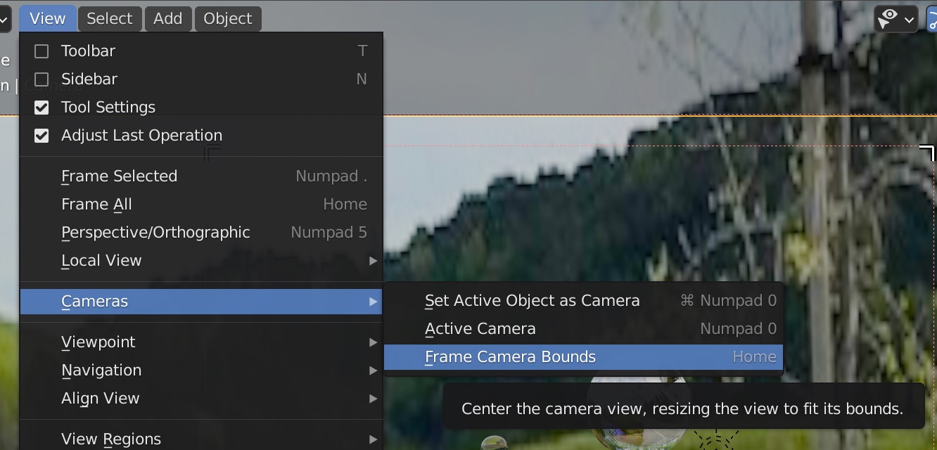 Then if you want to adjust the resize the bounds smaller, temporarily disable
N ➤ View ➤ View Lock ➤ Camera to View
then zoom out with the middle mouse wheel.
Then if you want to adjust the resize the bounds smaller, temporarily disable
N ➤ View ➤ View Lock ➤ Camera to View
then zoom out with the middle mouse wheel.
Resizing the Render View
If you are doing Cycles rendering in the camera view, you can resize the render area smaller within the camera frame. Select the camera in the Outliner Panel. The window borders will show up, and you can drag them.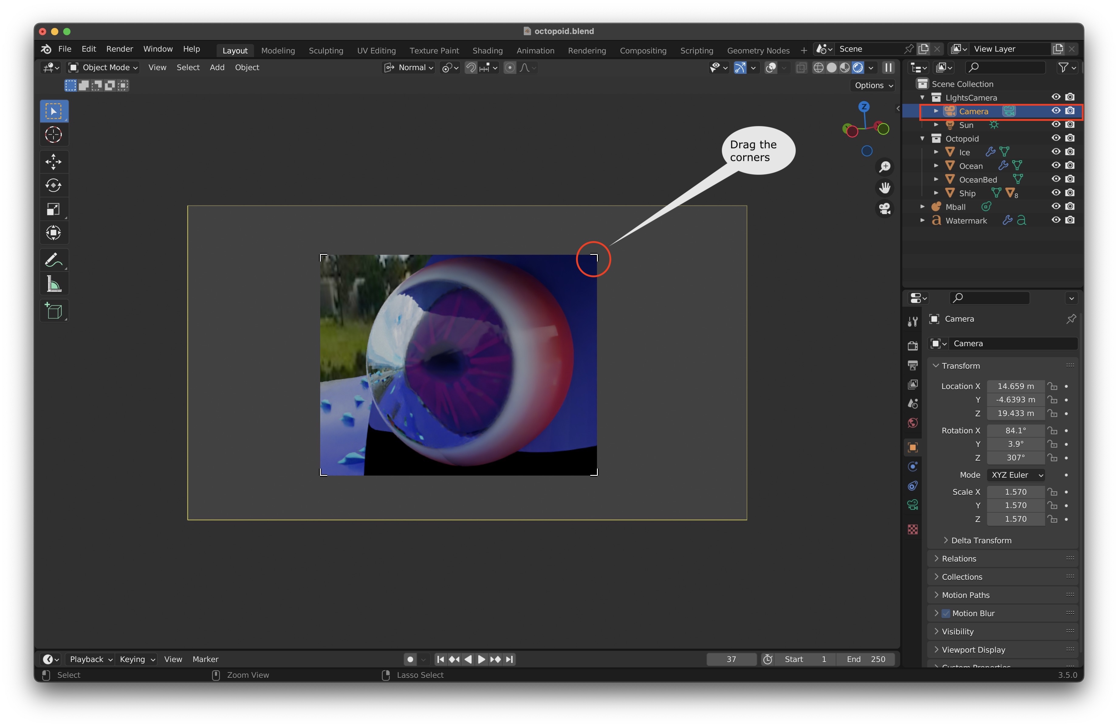
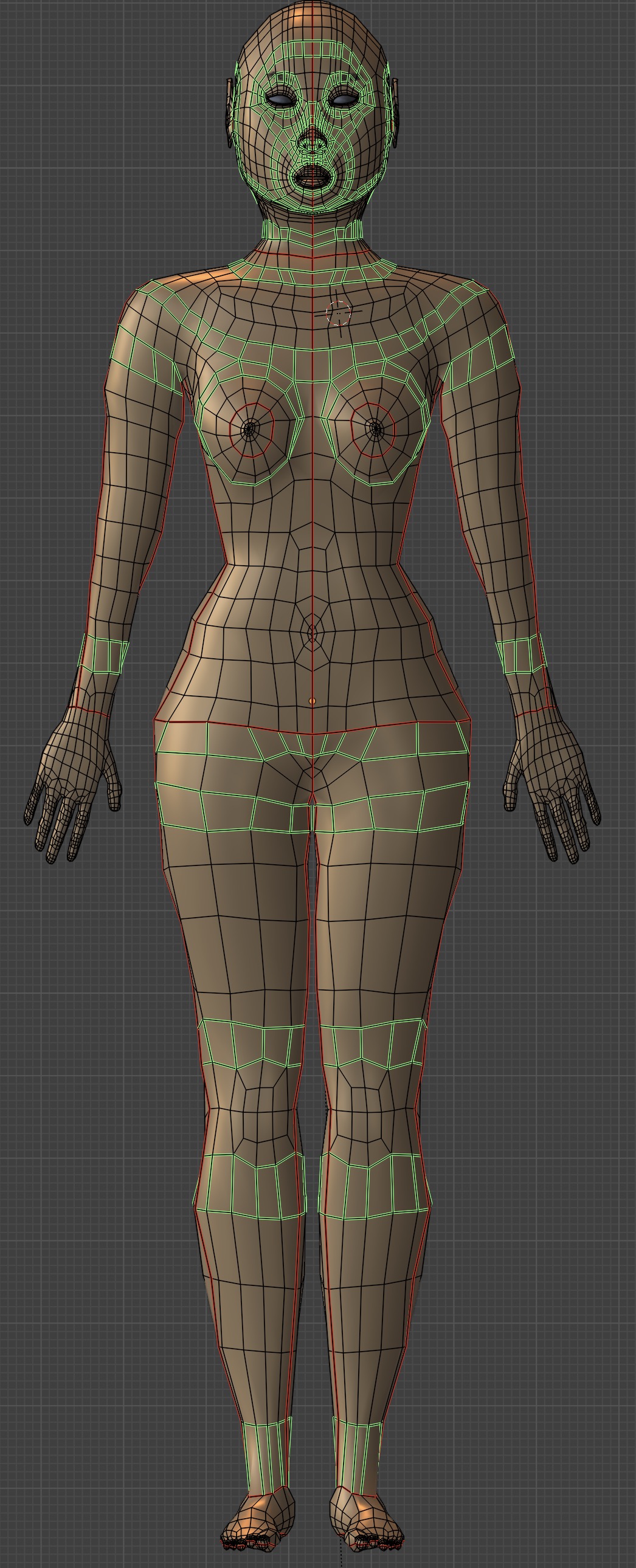
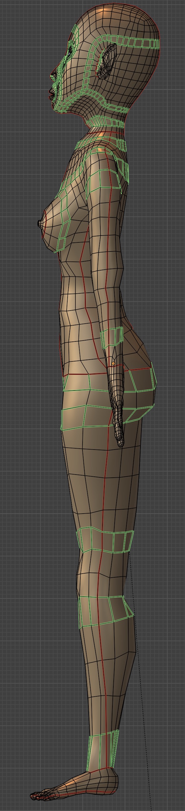
Modeling
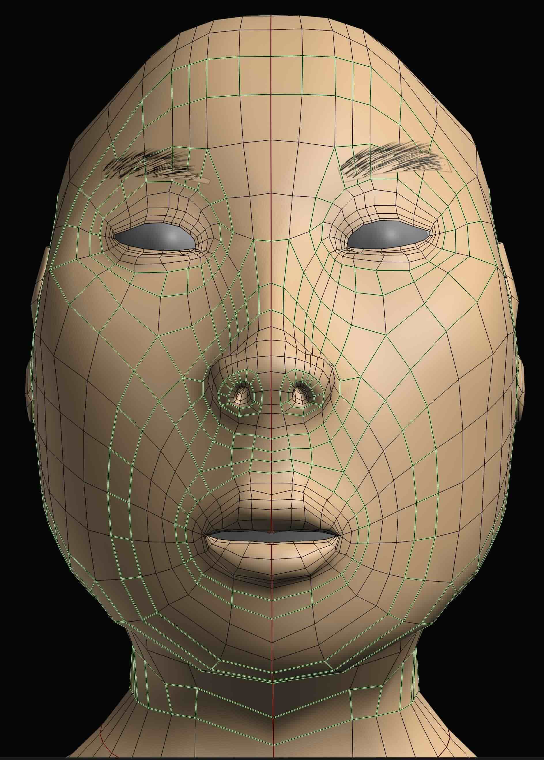
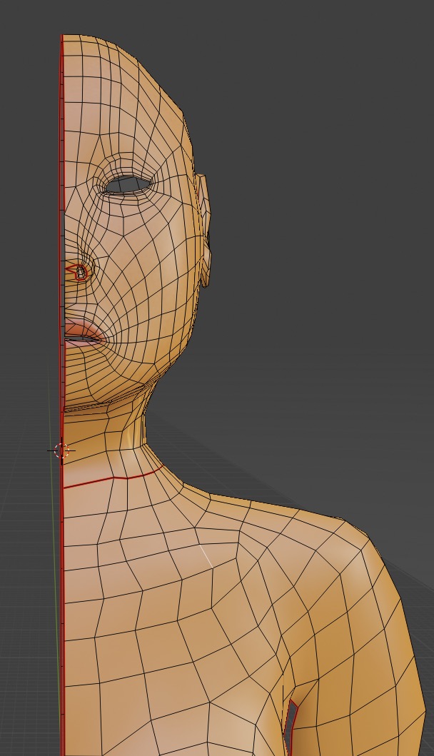
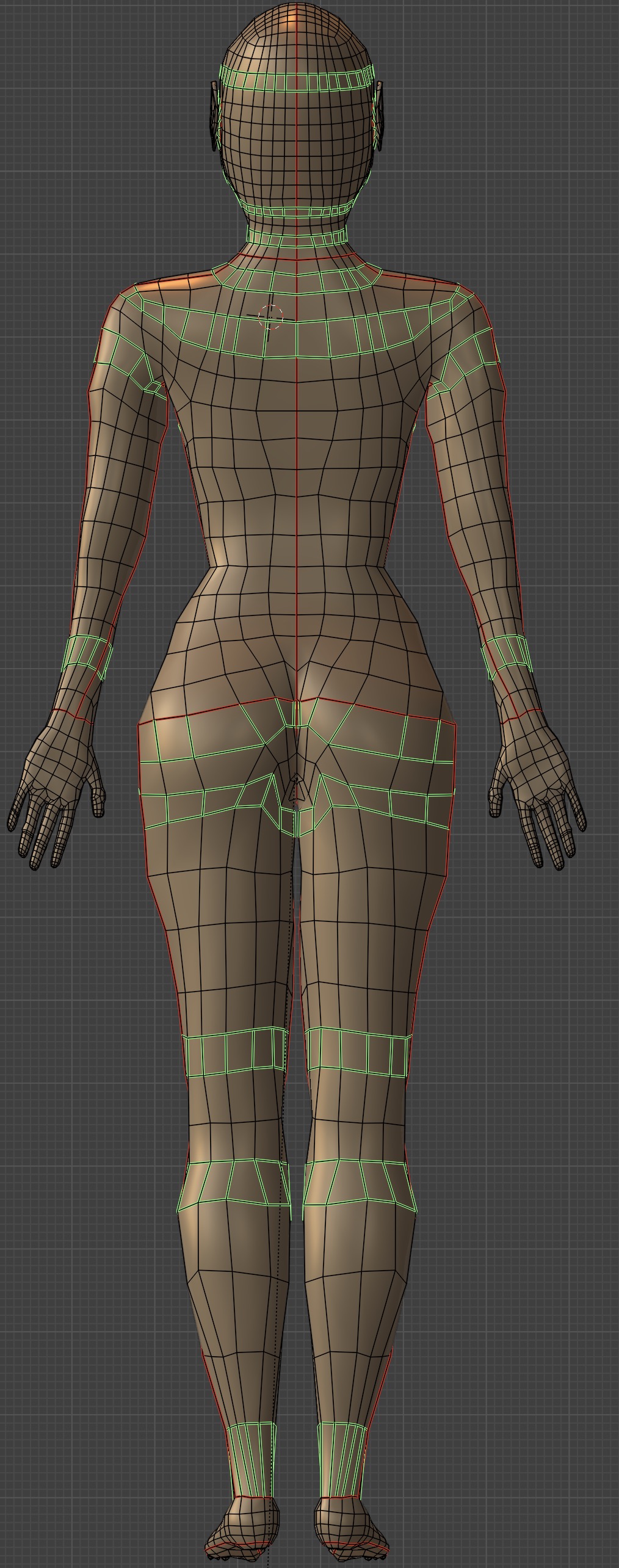
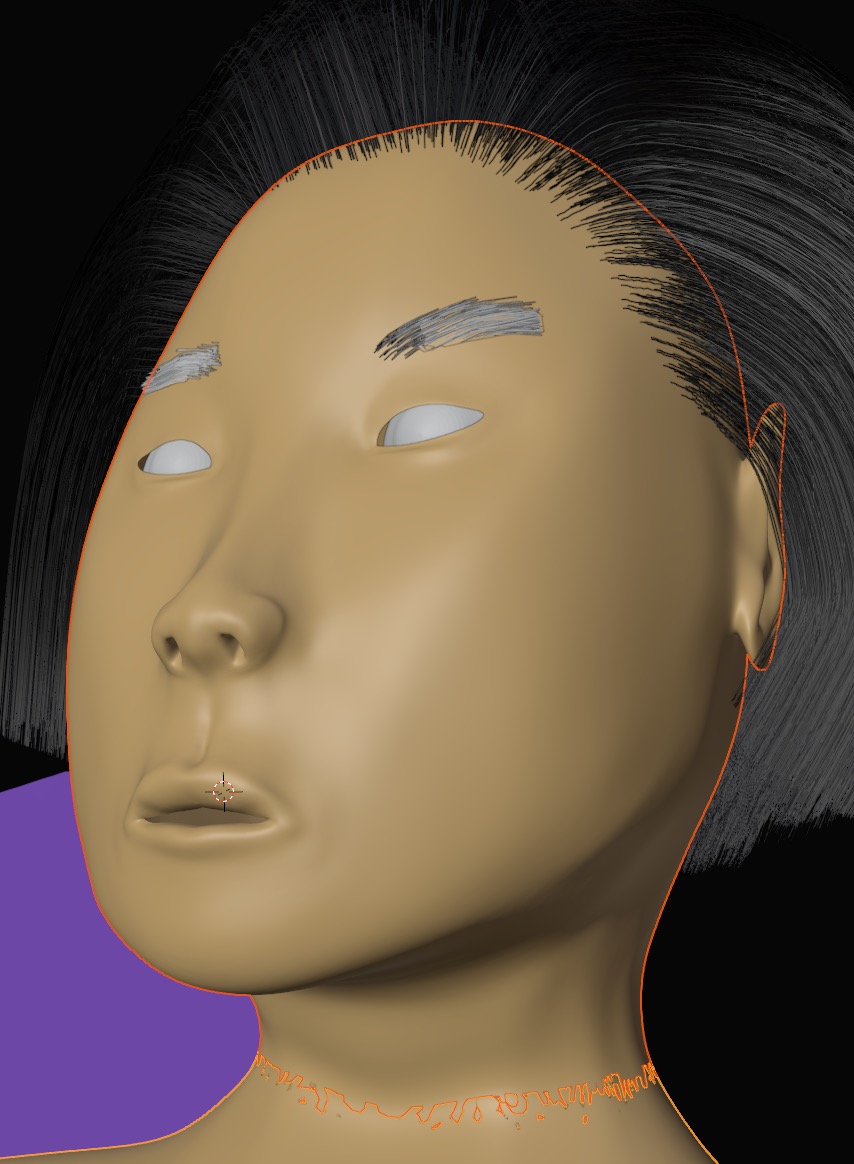
We'll illustrate modeling in the Modeling Workspace with a female figure mesh which I did as a study for a painting,
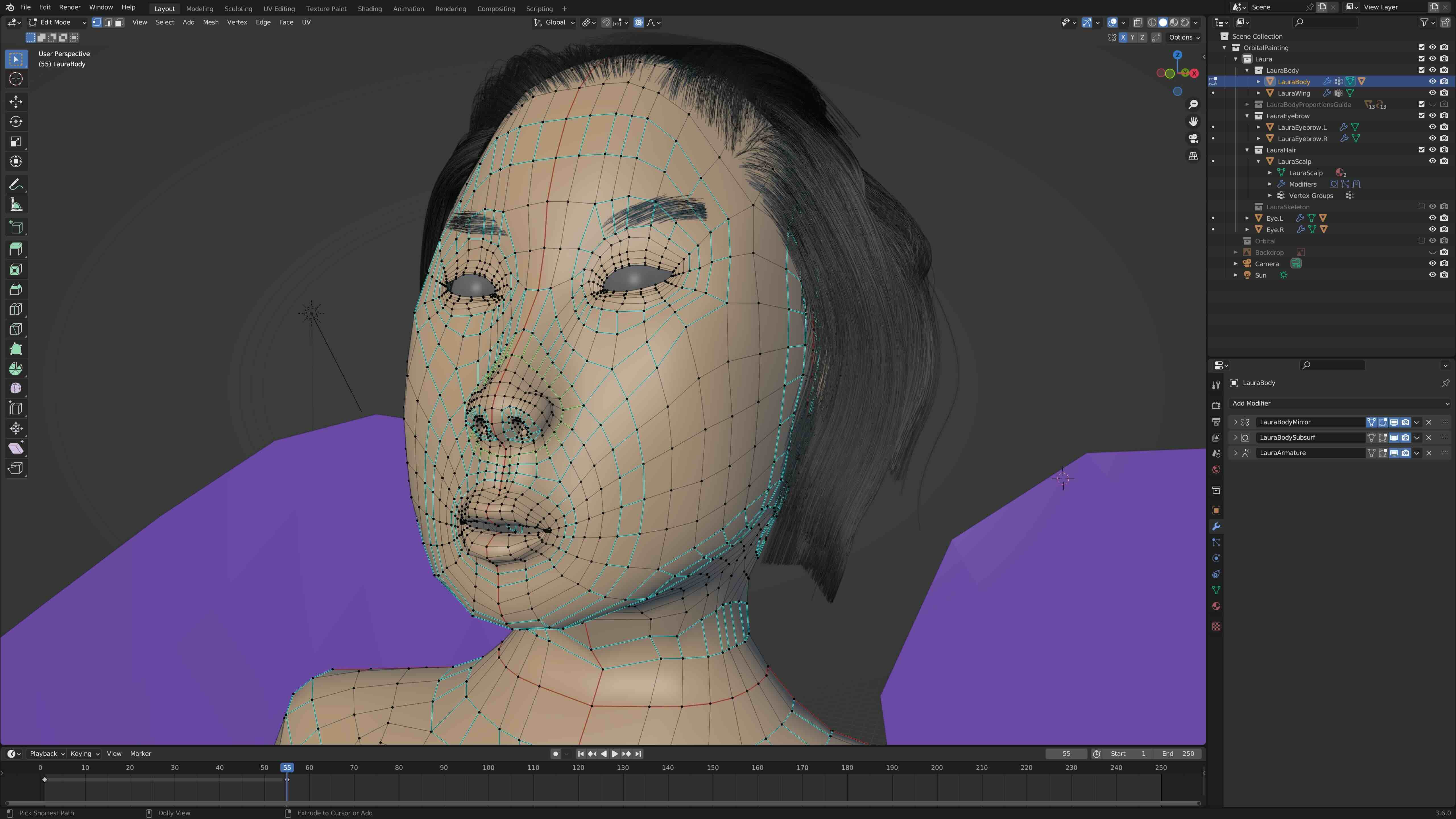
The basic idea is to use edge loops which follow muscles, tendons and bones so we can animate the figure more easily after rigging and skinning it.
Topology
It's important to use polygons with a low number of vertices to make modeling simpler and figures more flexible and to use square faces (quads) whenever possible to make surfaces render more smoothly. We can use a limited number of poles (i.e. vertices with 5 edges) when joining edge loops.
Commands for Editing the Mesh
| Hot Keys | Action | Description |
|---|---|---|
| x | Delete edges / faces / vertices | Pick which type to delete from menu. |
| double click Left Mouse Button | Edge or face loop select. | Depends on whether edge or face seleection is active. |
| CTRL R, click left mouse button, move cut with mouse, RETURN to accept | Mesh cut | Subdivide the mesh with a cut |
| F | Generate faces. | Create faces between edges and vertices. |
| O | Proportional editing toggle | You can alteratively use Sculpting mode. |
| L | Select connected part of the mesh; stops at seams | Works in uv mapping also |
| Ctrl E ➤ Edge Slide | Slide Edges | |
| Select part of mesh in edit mode then P ➤ Selection | Split off selected mesh as new object. | Exit Edit mode to see the new object. |
| M ➤ Merge at Center or M ➤ a | Merge vertices | Can use to integrate a new submesh into a hole in the mesh. |
| Alt S mouse | Move vertices normal to faces | |
| V | Rip Vertices, edges, apart | Separate one edge into two to open a hole. |
| Control z | Undo last command | You can keep repeating this command |
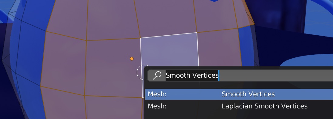
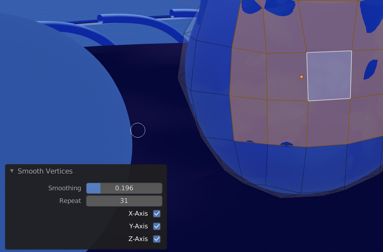
To smooth vertices select them in edit mode. Then invoke Ctrl-V ➤ Smooth Vertices and you can select the degree of smoothing and number of iterations in the pop-up menu.
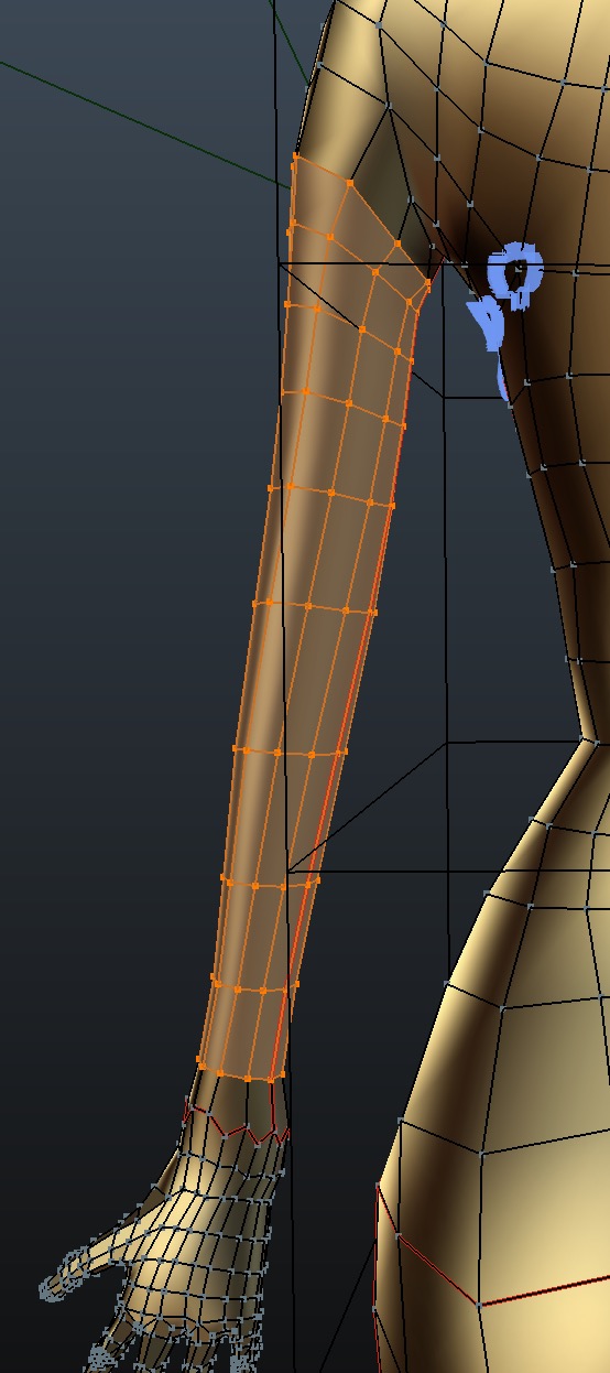
To select interior of a mesh you can select two edge loops on opposite ends of an object, such as this
arm, using
Double Click Left Mouse Button for the first loop,
SHIFT Double Click Left Mouse Button for the second loop,
then select the region between using
Search Menu ➤ Select Loops ➤ Select Loop - Inner Region (recall I assigned space bar for the search menu).
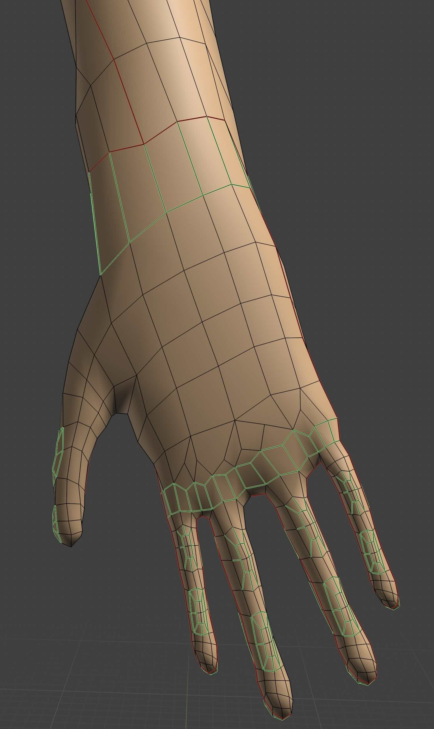
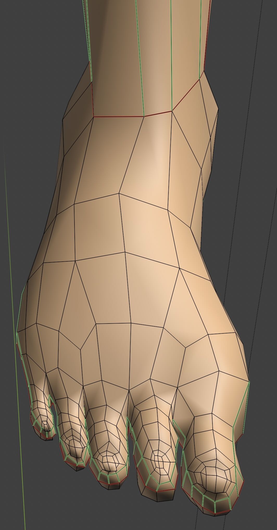
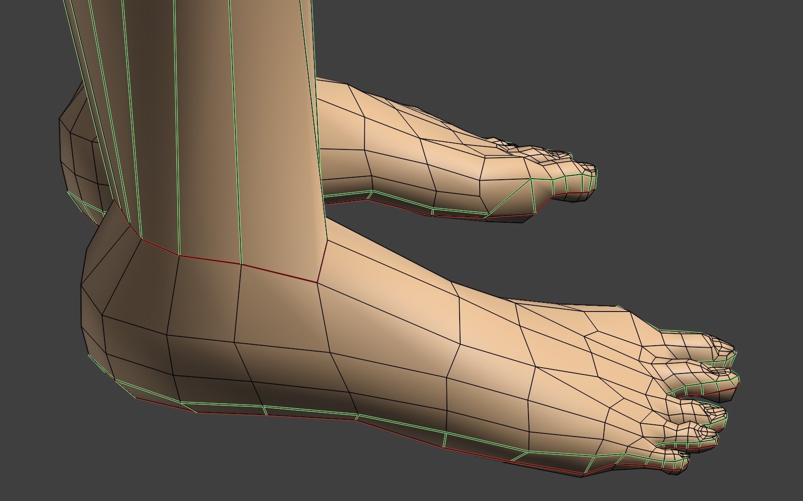
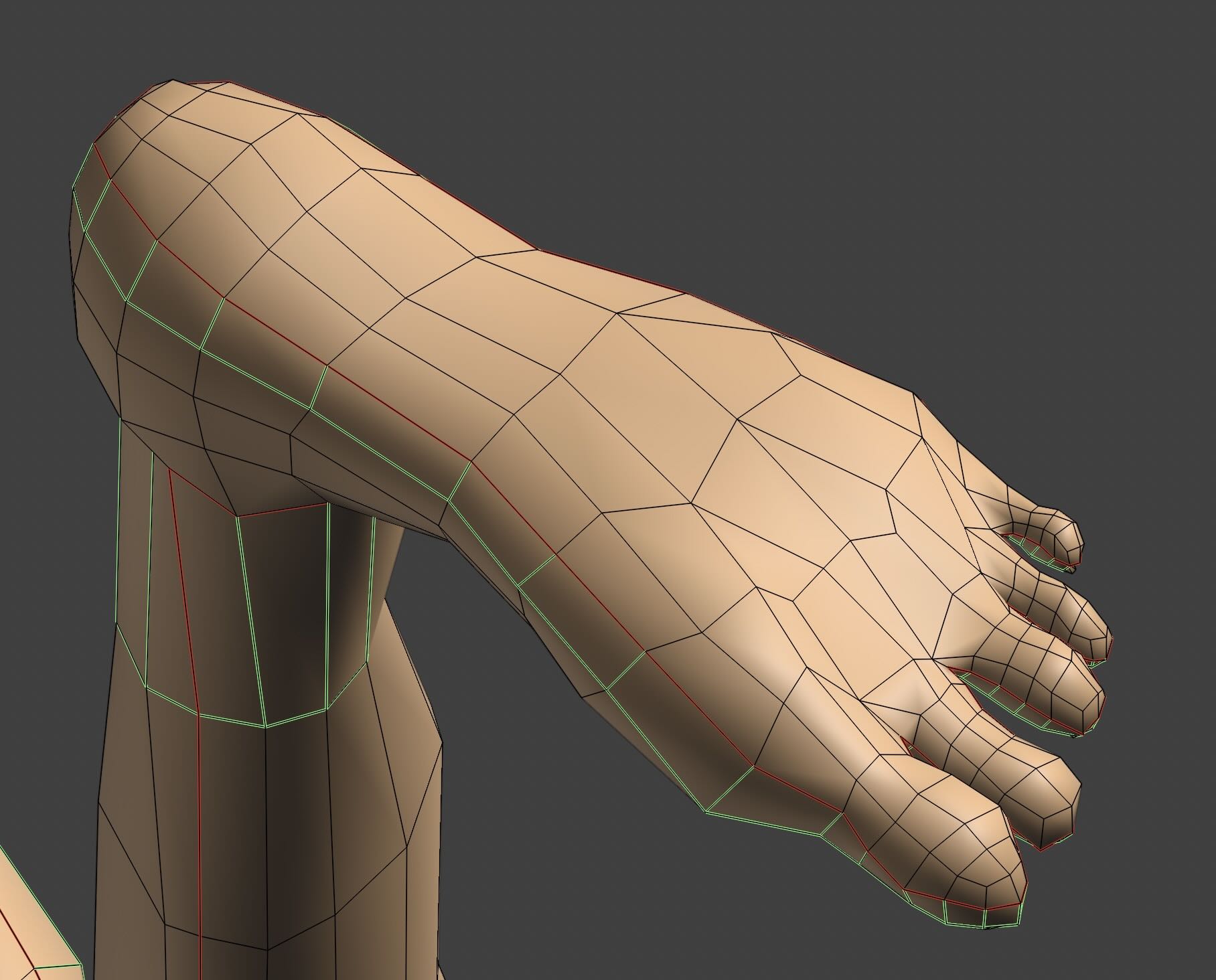
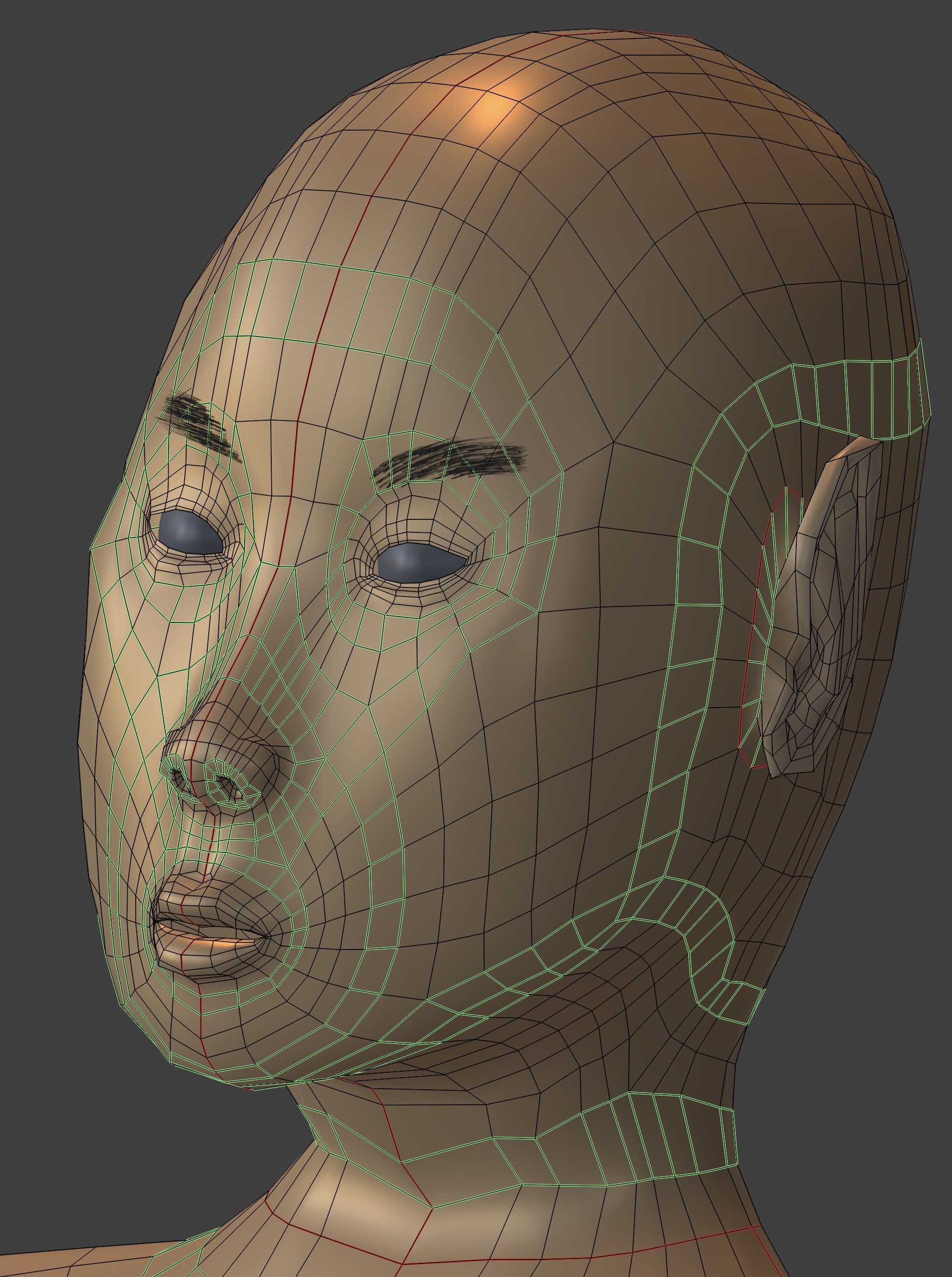
Face Loops; also Hands and Feet
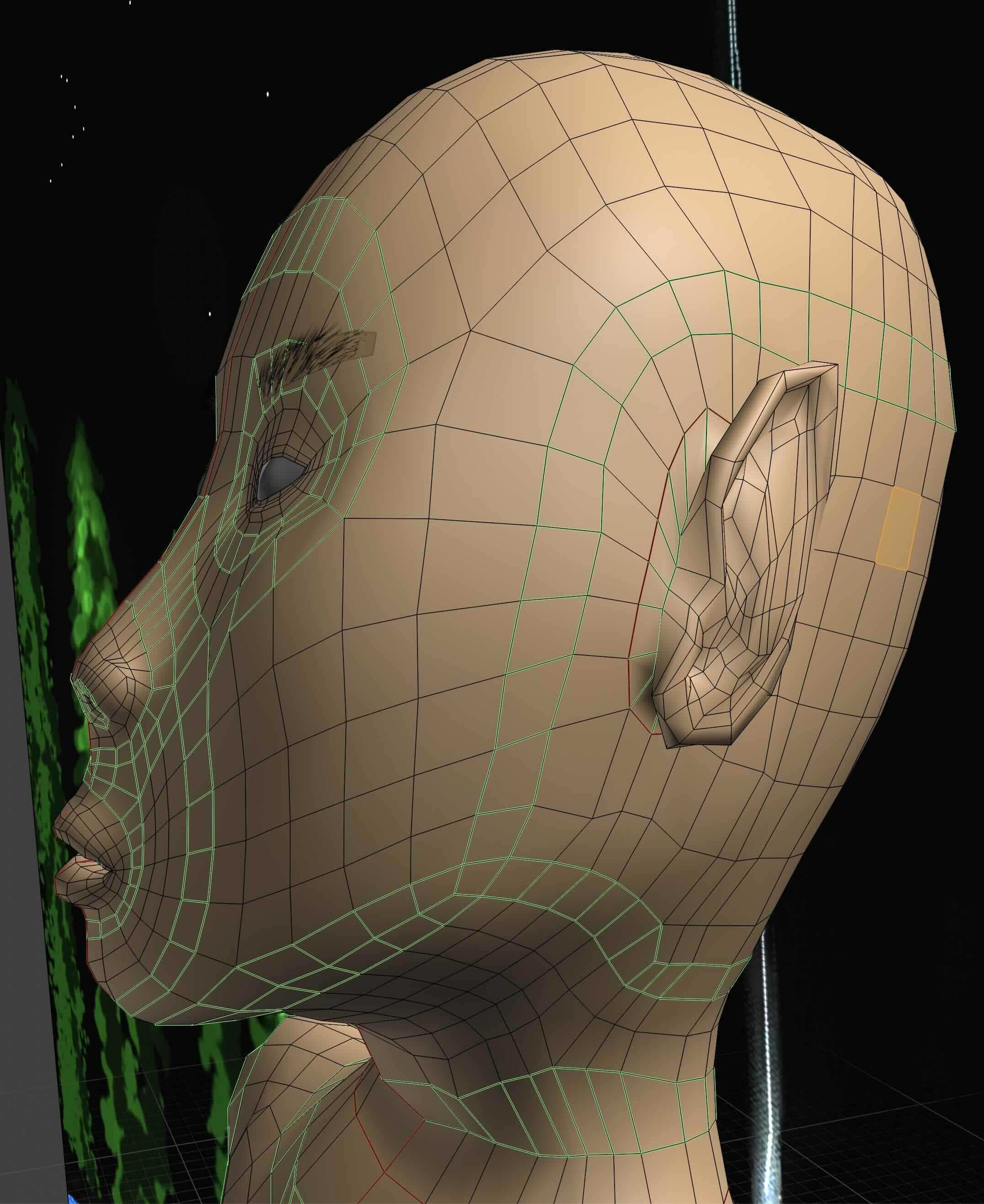
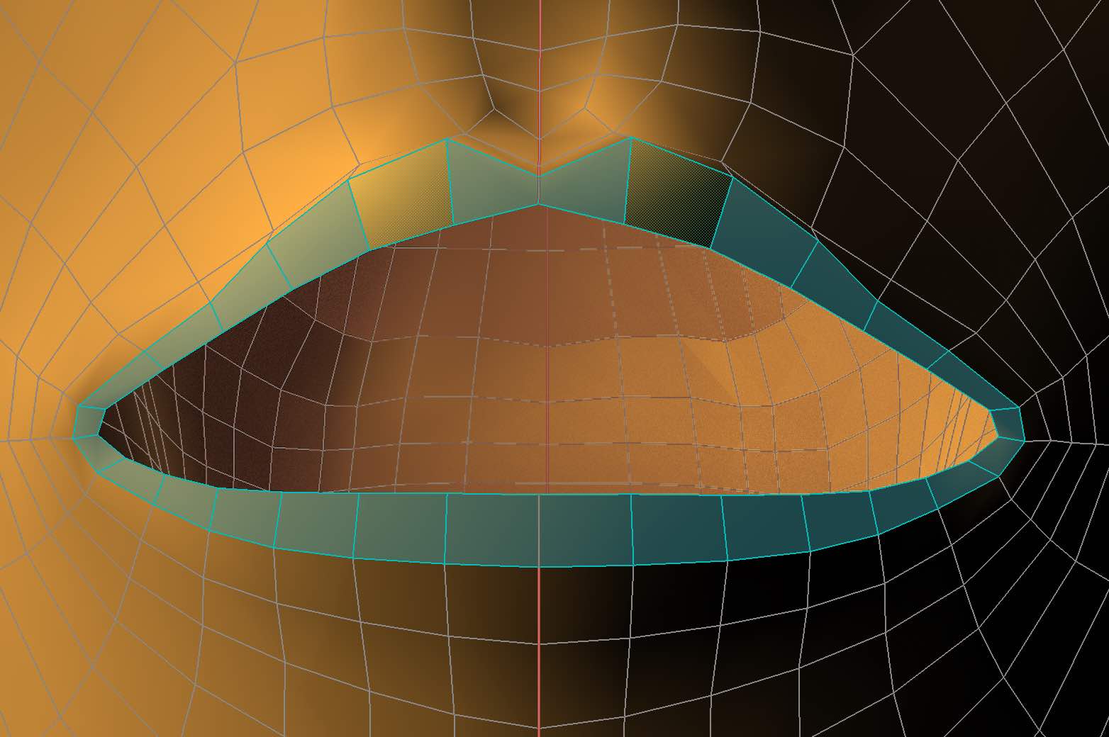
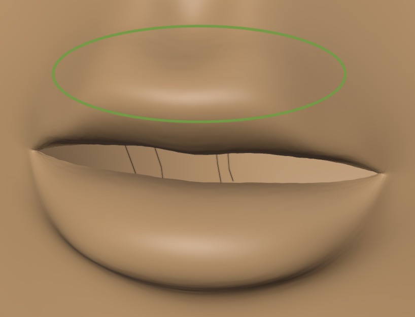
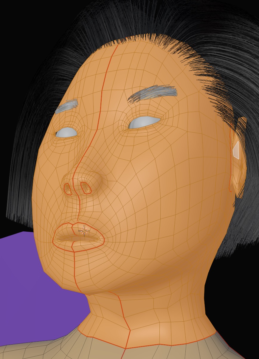
Face loops on my model's face following muscles around the eyes, lips, and jaw. Feet and hands have their own set of loops.
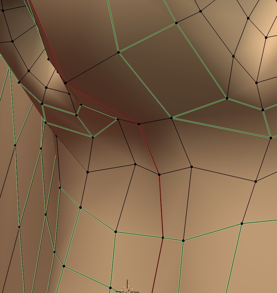
To color the edge loops green, select a loop using Double Click Left Mouse.
Then color the edge using Ctrl E ➤ Mark Freestyle Edge, which you can shorten to Ctrl E y
(Red edges are seams used for UV unwrapping).
Extruding From Face Loops
Start with the face loop for lips. Extrude several times to create the lips.
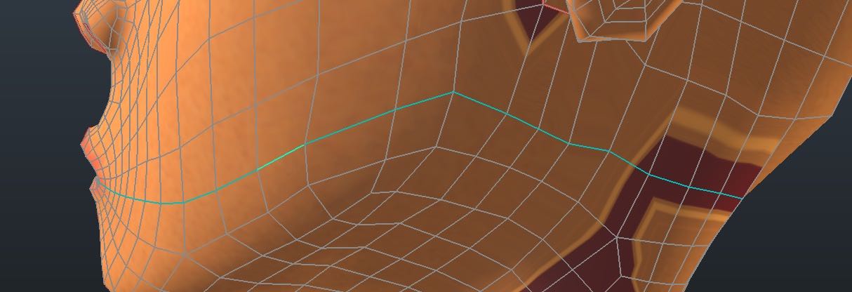
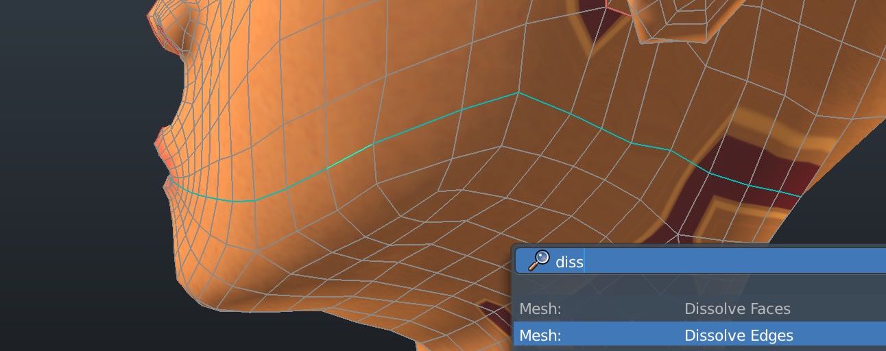
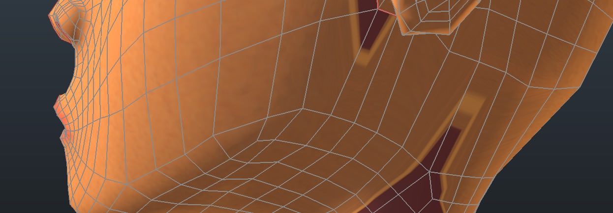
Dissolving Edges
Simplify the mesh by dissolving edges. Select the edge loop with
Double Click Left Mouse Button then remove it with
Right Click Mouse ➤ Dissolve Edges
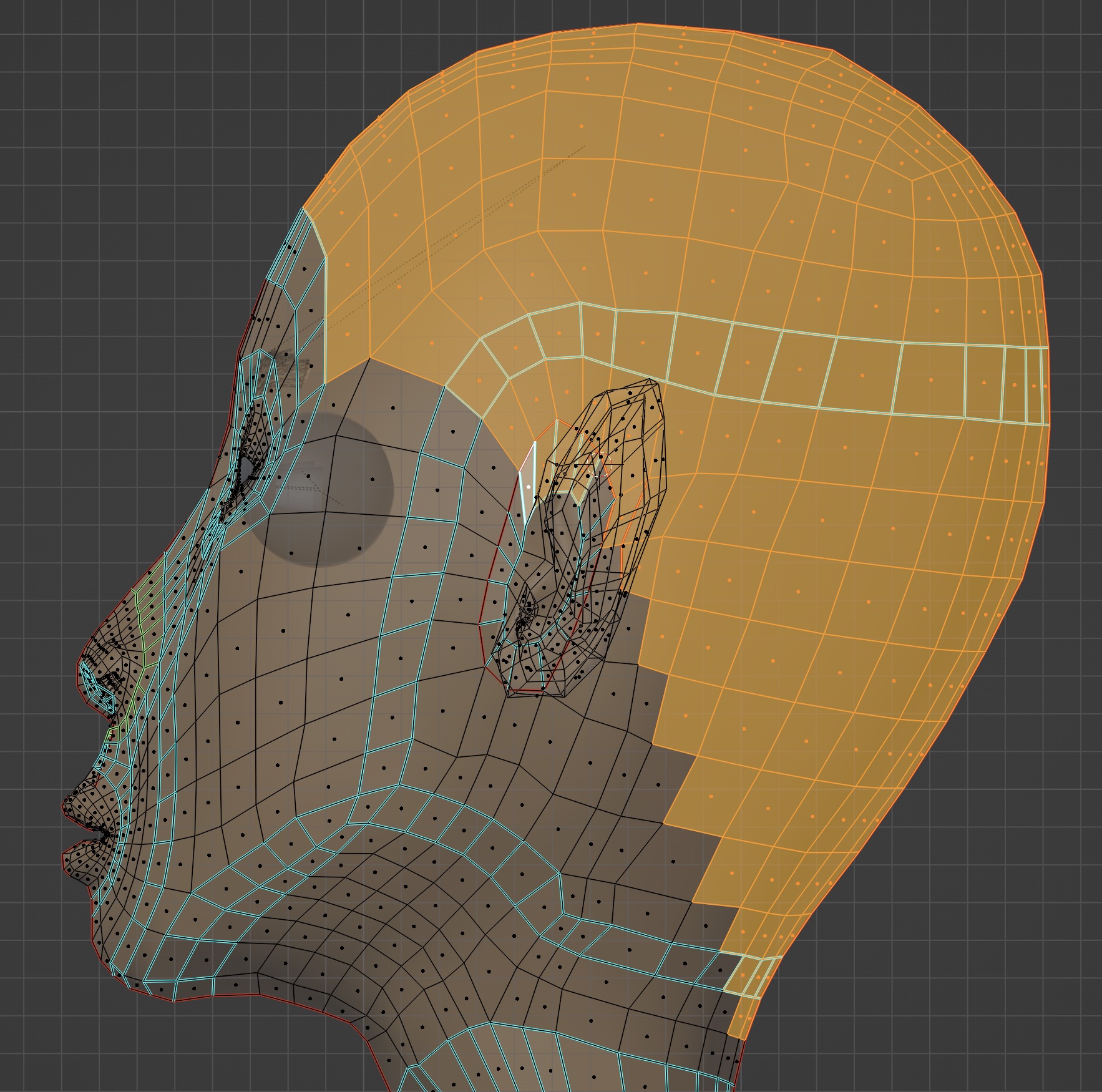
Hiding Portions of the Mesh
I want to work on the mesh behind the ears by temporarily hiding them.
First Double Click Left Mouse Button to select an edge loop which
joins the ear to the head.
Bring up the Search Menu (recall I assigned space bar for this).
Search for "Select Loop Inner".
Then choose Select Loop Inner Region to select the entire ear mesh.
Do H to hide the ear. Once we are done, unhide the ear again with
Alt H.
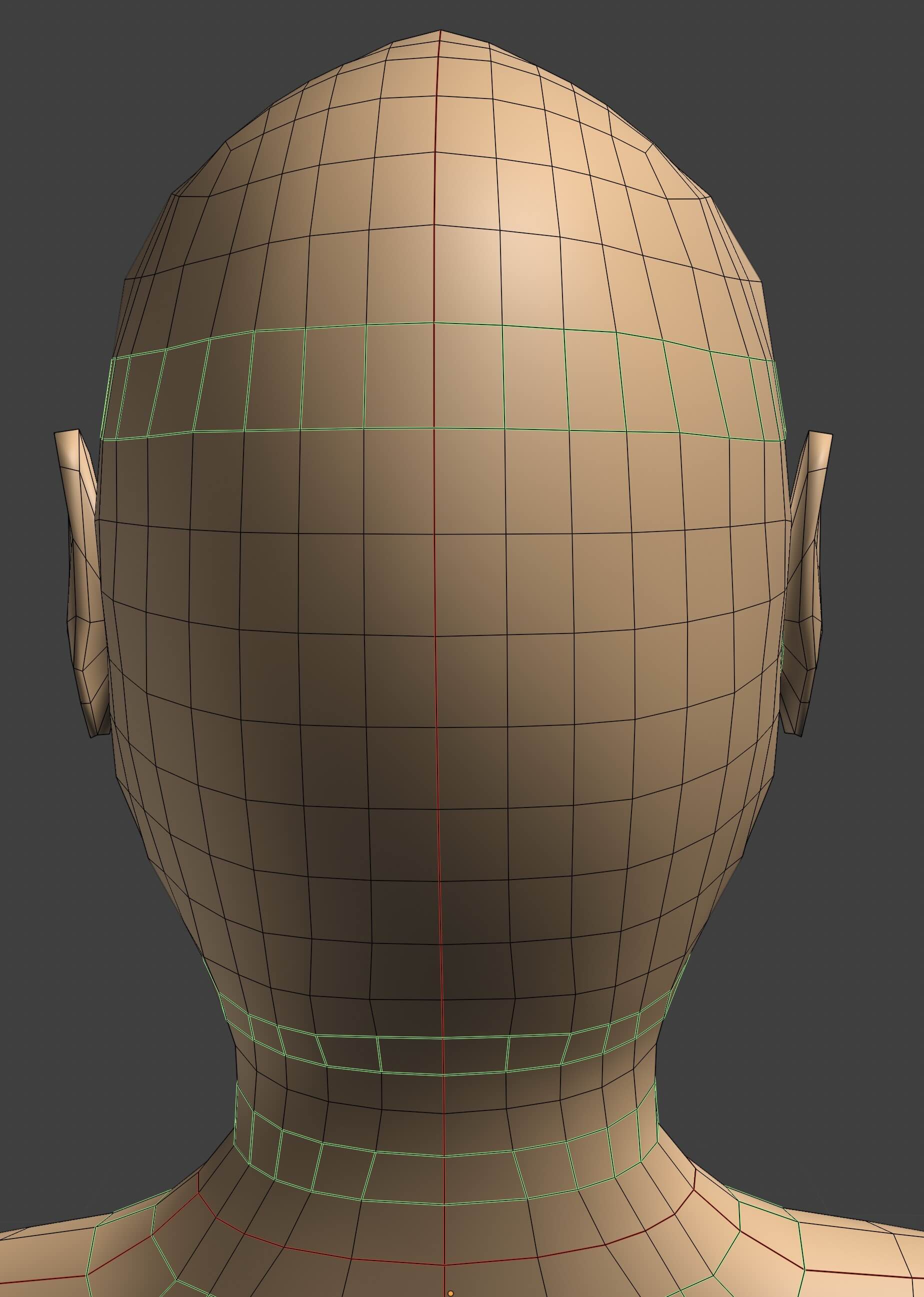
Mirroring the Mesh
I created only half of the mesh as a shortcut since the human body has mirror symmetry
 That's done by adding a mirror modifier (move the mirror modifier up the stack before the
subsurf modifier), and mirror in the x axis.
That's done by adding a mirror modifier (move the mirror modifier up the stack before the
subsurf modifier), and mirror in the x axis.
But before you do this, first set the body object scale is set to 1 and the rotations to zero using Ctrl A ➤ Apply Rotation and Scale
And secondly, the mirror plane must be the centered exactly, i.e. the local origin must be correctly positioned. See the Blender Manual: Accurately Positioning the Mirror Plane I'll repeat the method here. Go into Edit Mode. Select the left edge loop on the half figure Double Click Left Mouse Then Shift S ➤ Cursor To Selected puts the 3D cursor at the center of the edge. Go into Object Mode. Bring up the Search Menu (recall I assigned space bar for this). Search for Set Origin ➤ Origin to 3D Cursor which puts the object origin (and thus, the mirror plane) to the 3D cursor.
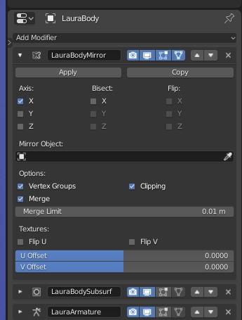
Add the mirror modifier.
In the Mirror Modifier Panel, enable Clipping, and
set the Merge Limit to 1mm which is
the smallest value which causes vertices along the mirror line to snap together without a seam.
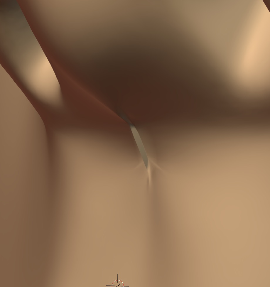
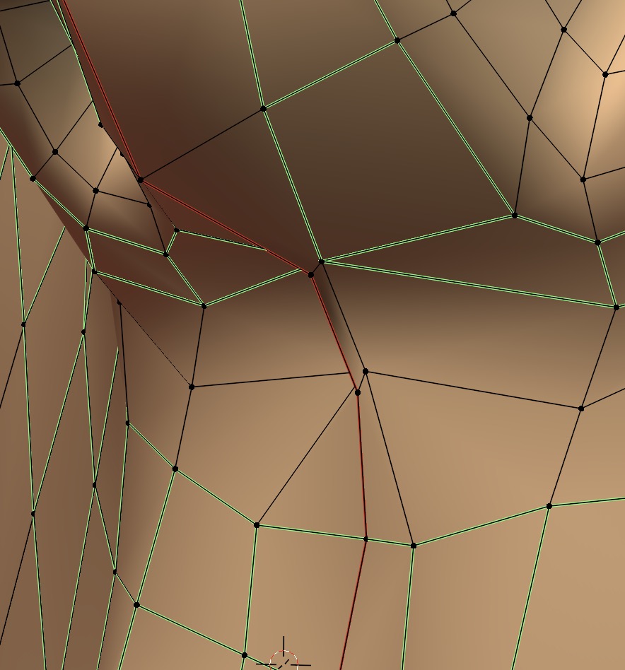
You may get a seam if you adjust the merge limit too large (10mm):
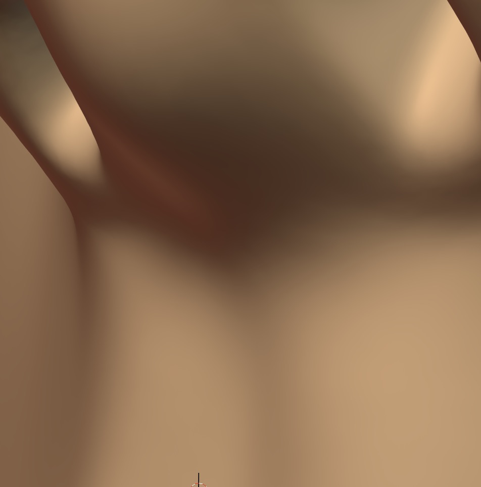
The seam disappears if you adjust the merge limit smaller (2mm):
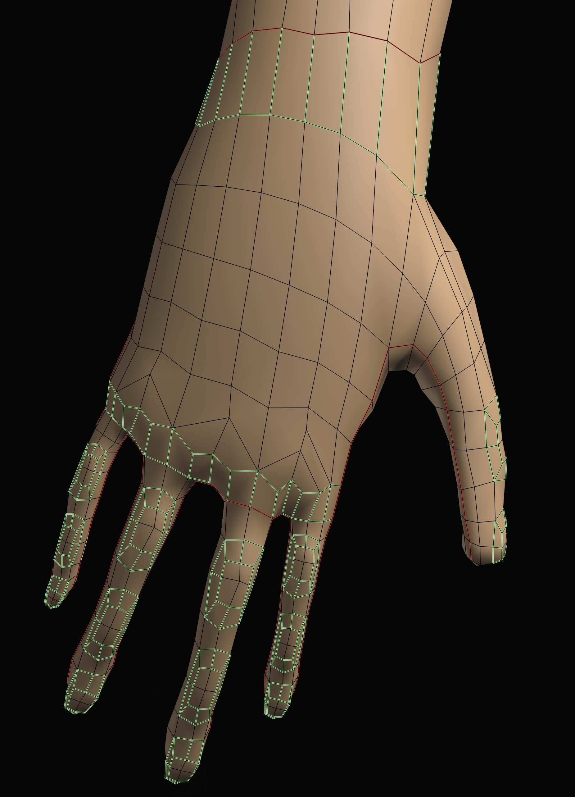
Duplicating Finger Mesh by Copying and Pasting Mesh Geometry Within the Same Object
After you've modelled one finger, you can simply duplicate the mesh geometry to create the other fingers. Select a portion of the finger mesh with B when dragging the mouse. Selection is faster if you toggle on X-Ray mode Option Z because you can select both sides of the finger at the same time. Duplicate with Shift D then immediately drag the duplicate away from the original with the mouse. Move it into place at the new location and connect the edges. You can use L to select the finger mesh. Note that all portions of the mesh are still connected to the same object.
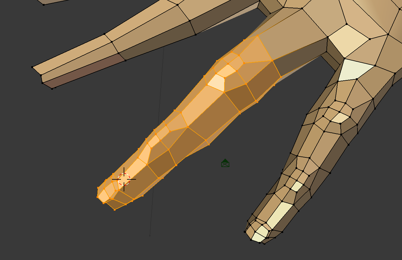
- Select a finger mesh from the hand.
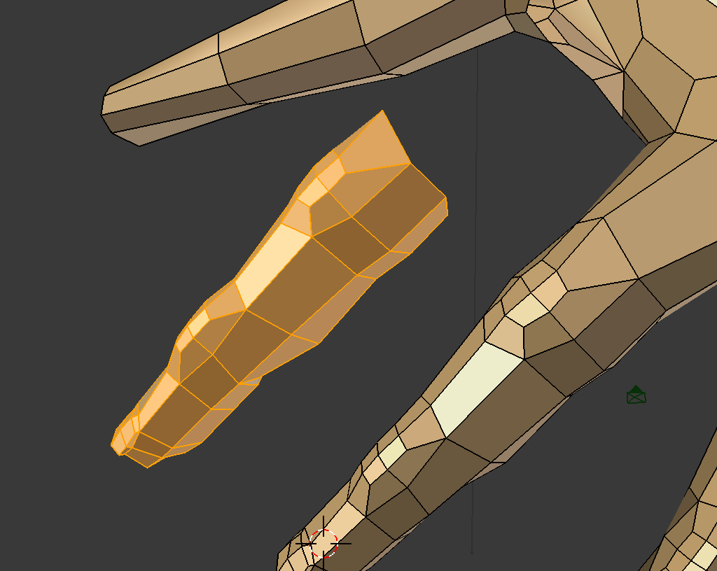
- Move the copy into place on the other hand.
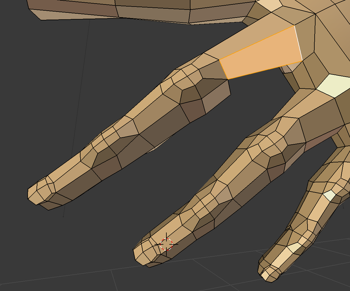
- Connect the copied finger to the hand.
Fixing Inconsistent Normals
If you have odd looking pieces in the object, your normals may be inconsistent.
Go into edit mode, select the entire mesh with
A, then
Recalculate Normals with Shift N
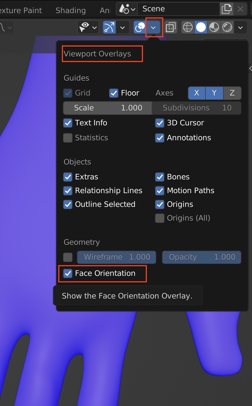
You can double check in 3D View by toggling on
Viewport Overlays ➤ Face Orientation
You should see a the object color as usual, but you will see a red color where normals are pointing the wrong way to the inside.
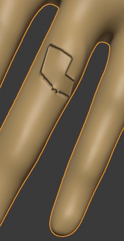
Removing Duplcate Vertices
Duplicate vertices can cause the object surface to look pinched or folded.
To fix this go into mesh mode with TAB and select all vertices with A then do Mesh ➤ Clean Up ➤ Merge ➤ By Distance
Now it's fixed!
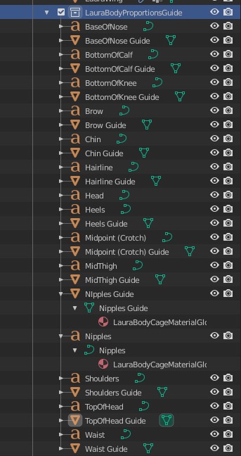
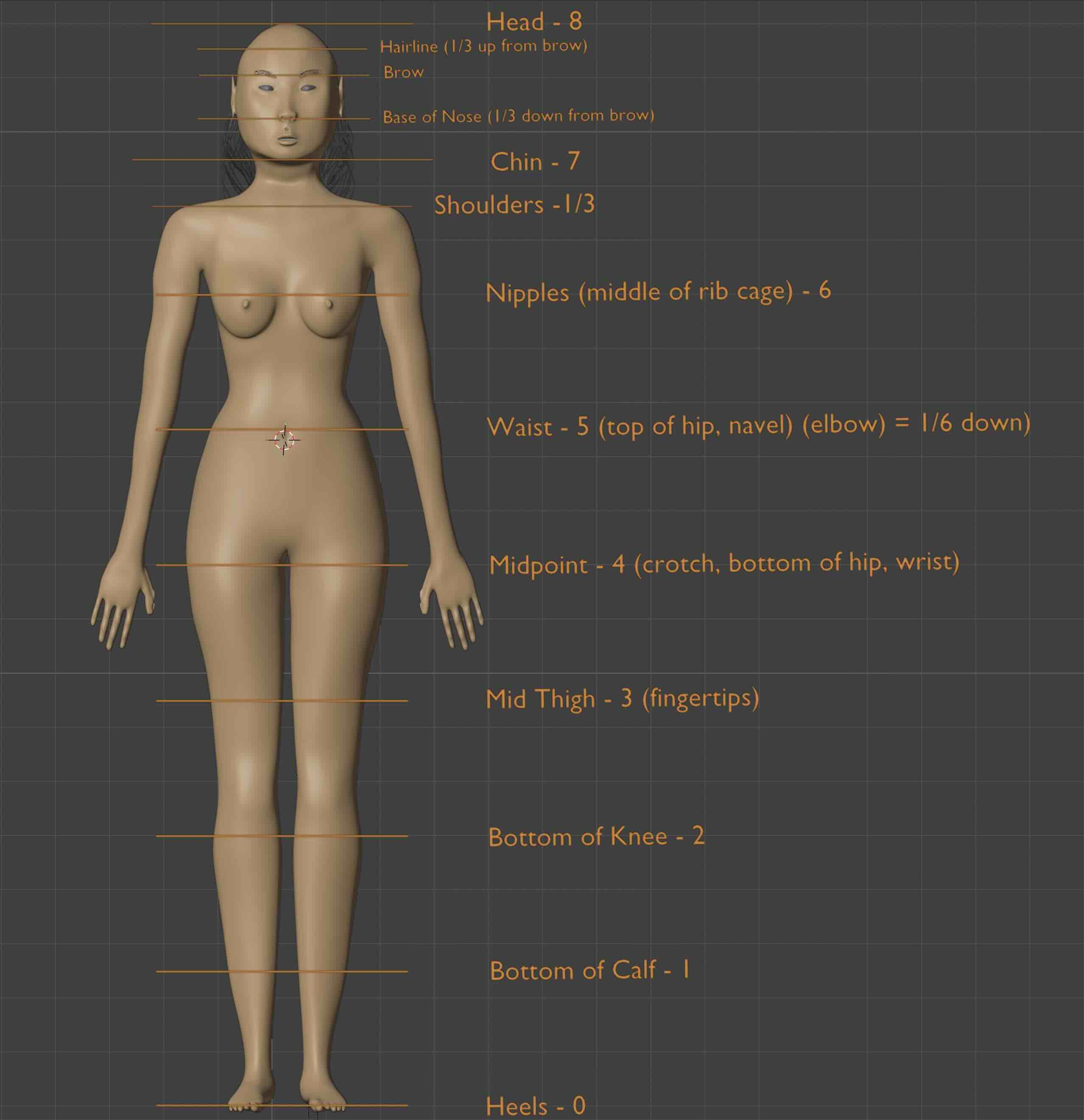
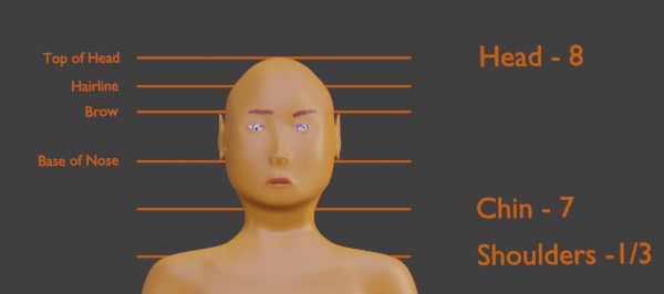
Body Proportions Guide
I created a body proportion guide by creating a plane, deleting its face, and extruding its edges to give some thickness
so we can see it.
Then repeat many times to get all the guide bars:
Shift D to duplicate and g z to move up to the correct position.
Then create text for all the guide bars in the same collection with the same orange emission node material.
Edit mode lets you use the keyboard and arrow keys to edit text. The usual resize object commands will work.
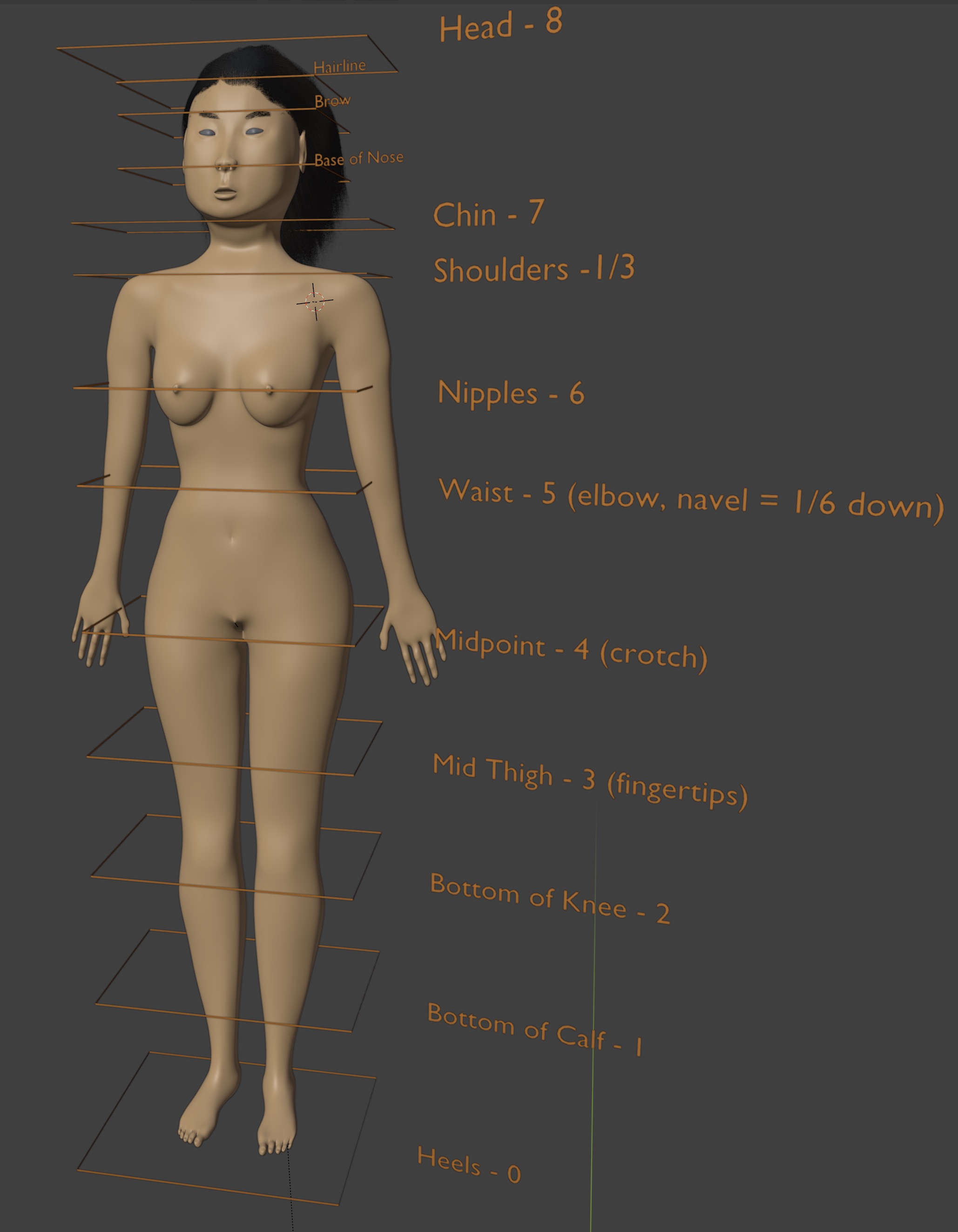 You can adjust the proportions more easily in Orthographic Projection Mode mode which gives you a grid
to adjust your figure's dimensions. Use 5
to toggle from perspective view to orthographic view and 1 to center the view facing forward.
You can adjust the proportions more easily in Orthographic Projection Mode mode which gives you a grid
to adjust your figure's dimensions. Use 5
to toggle from perspective view to orthographic view and 1 to center the view facing forward.
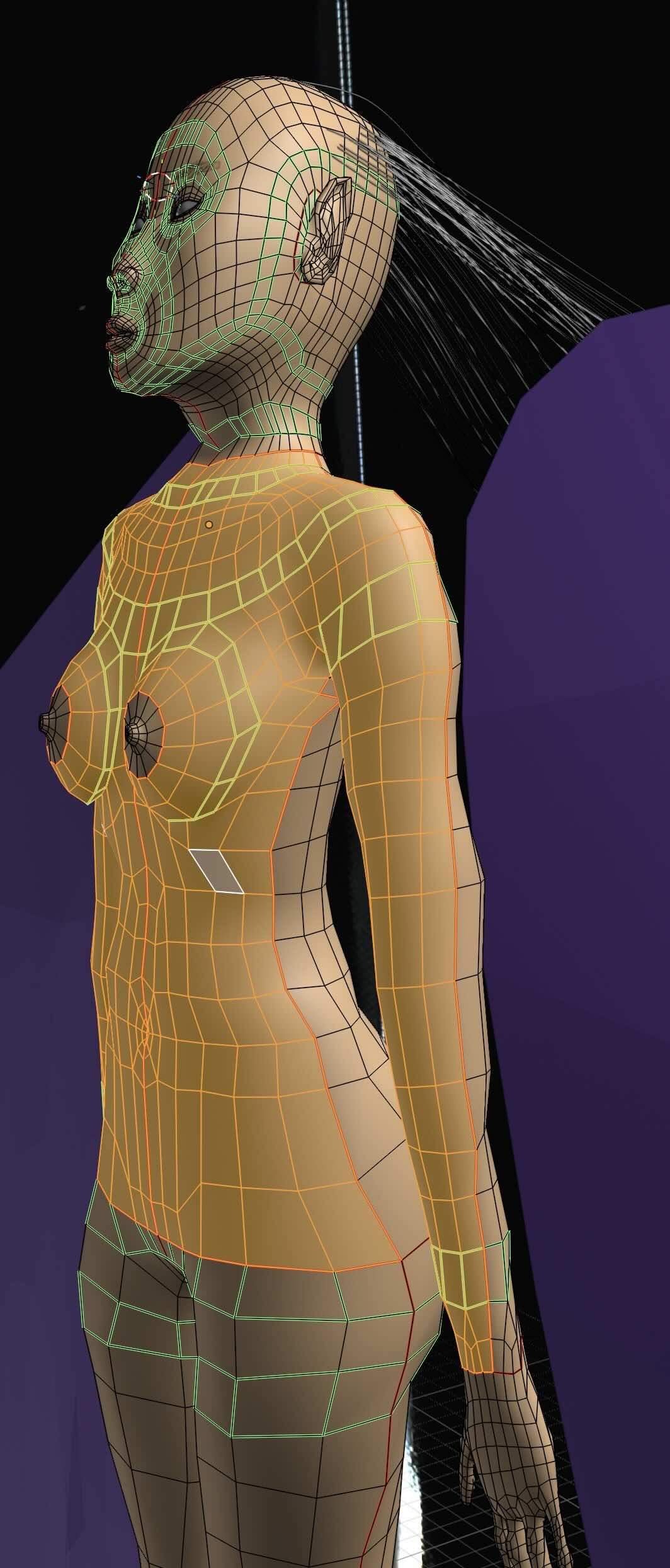
 If the figure skin looks strange in Viewport Shading ➤ Materials Preview (Evee mode)
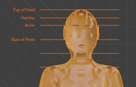 toggle on Material Properties ➤ Viewport Display ➤ Settings
➤ Backface Culling
toggle on Material Properties ➤ Viewport Display ➤ Settings
➤ Backface Culling
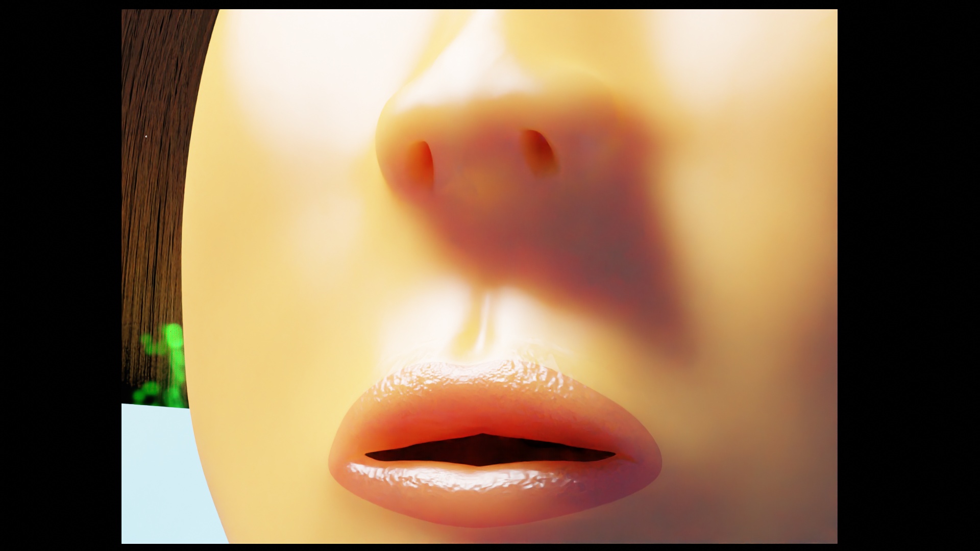
Skin
Making realistic skin is hard -- we'll we'll do it in several steps.
- UV Mapping I did separate UV mapping of head and torso of the female figure to get more control over the skin colors and textures. Tricky: I use an alpha channel from the torso to make sure the colors stay separate and don't mix.
- Skin Color Painting Skin isn't a uniform color. So I start with flat images of skin color, then texture paint on top of them. These color images feed into the skin shaders color inputs.
- Skin Material Shaders I use a simplified model of skin material explained in Ben Simonds Three Layer SSS in Blender Demystified. and be sure to read Blender User Manual - Principled BSDF material node..
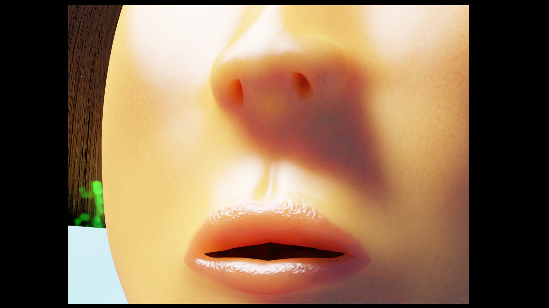
- Skin Texture using Normal Mapping Real skin has pores, bumps and wrinkles, especially on the lips. Texture painting is too flat and not realistic. So we need to duplicate the head mesh, create a high res copy of it, sculpt the hi res head to make wrinkles and other coarse skin texture. Then we bake this into a normal map image which we feed into all the skin shaders which apply this to the low-res head mesh. In other words, "faking" an actual hi-res mesh with its subtle height displacements, by perturbing the rendering ray tracing equations.
- Displacement Mapping would be more accurate than normal mapping. In particular, the silhouette of the head would be realistic, whereas the normal map silhouette will show up incorrectly as flat. But then, I'd have to use a hi-res mesh along with a corresponding hi-res grayscale displacement image where each pixel is the delta height of the object mesh. That would be slow to render, and a hi-res head mesh would be difficult to modify.
Marking Seams On the Mesh for UV Mapping
Mark seams along edge loops with Ctrl E ➤ Mark Seam on the figure so we will get a clean UV unwrap. The seams will show up as red edges in Edit mode (The green edges are face loops). I've followed the tutorial Unwrapping a Full Human Charactoer by CG Cookie
Head and torso are separated at the neck.
Arms are separated below the shoulder and up to the wrist; a less visible seam along the inner arm unfolds the arm like a cylinder.
Legs are separated out at the hips.
I've separated out smaller complicated parts such as the hands, feet, ears, nostrils, nipples.
Finally, there are seams on the hands and feet to so they unroll evenly.
To check the seams are partitioning correctly, go into
Edit Mode Face Select.
Select a face in the mesh then L to highlight all connected faces.
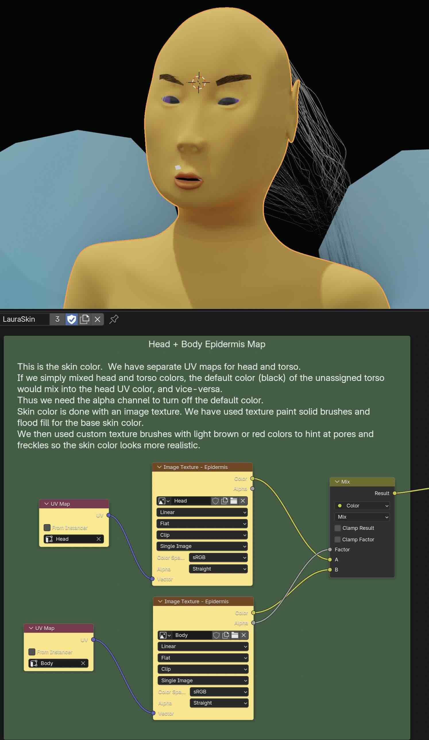
Separate UV Maps and Image Textures for Head and Torso
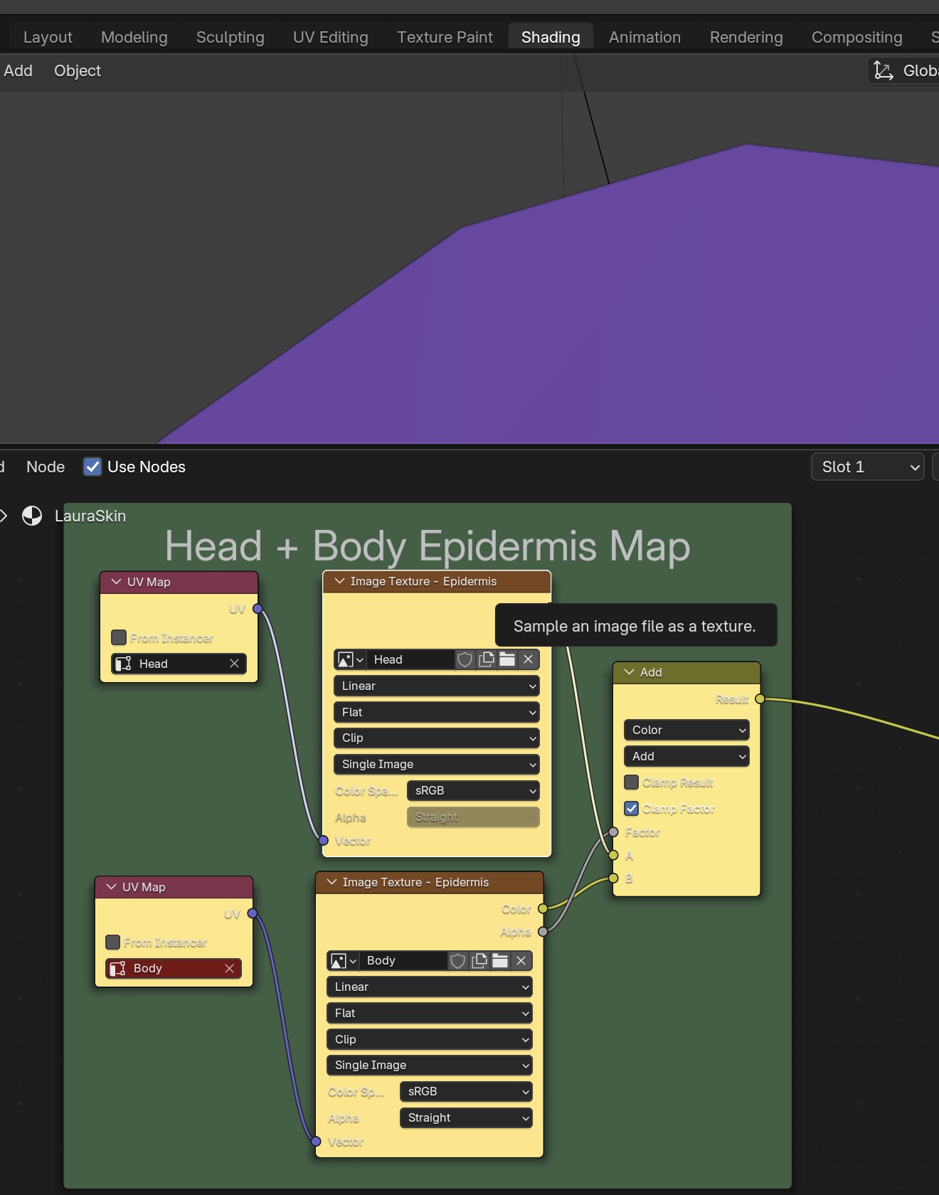
I created separate UV maps for head and body and combined them.
Simple color mixing with a constant factor won't work: it will just mix the color of the head UV map with the default
unassigned color (black) of the other body UV map. This is easier to see if we modulate the mixing factor from 0 to 1/2 to 1:
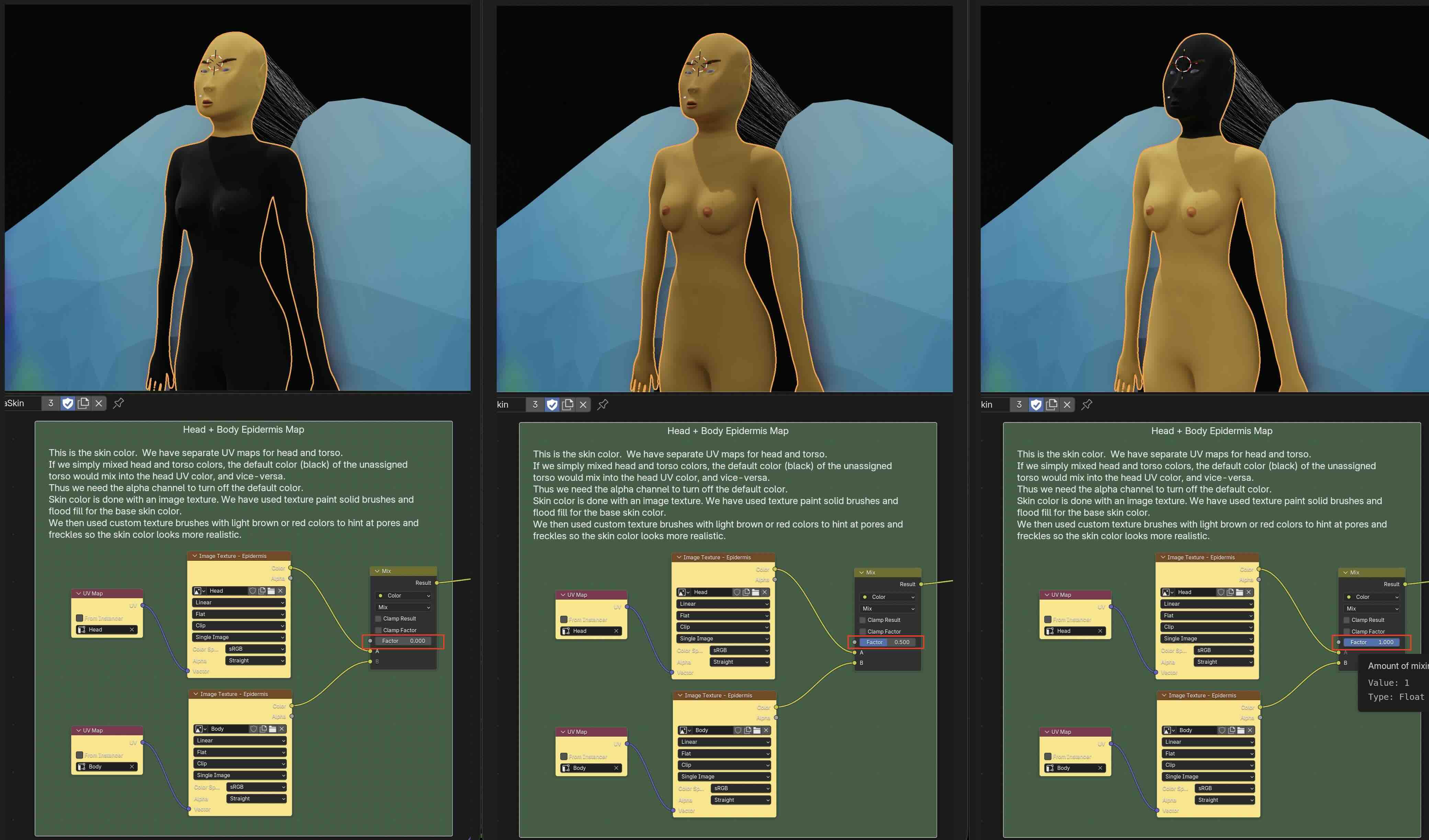
So instead, I hook up the alpha channel of the body UV map to the mix node factor input.
The body alpha channel will be 0 for the head and 1 for the body.
But that's just what we want! We'll add 100% of the head color (fac = 0) with 100% of the body color (fac = 1).
Now the head and body colors add seamlessly without overlapping.
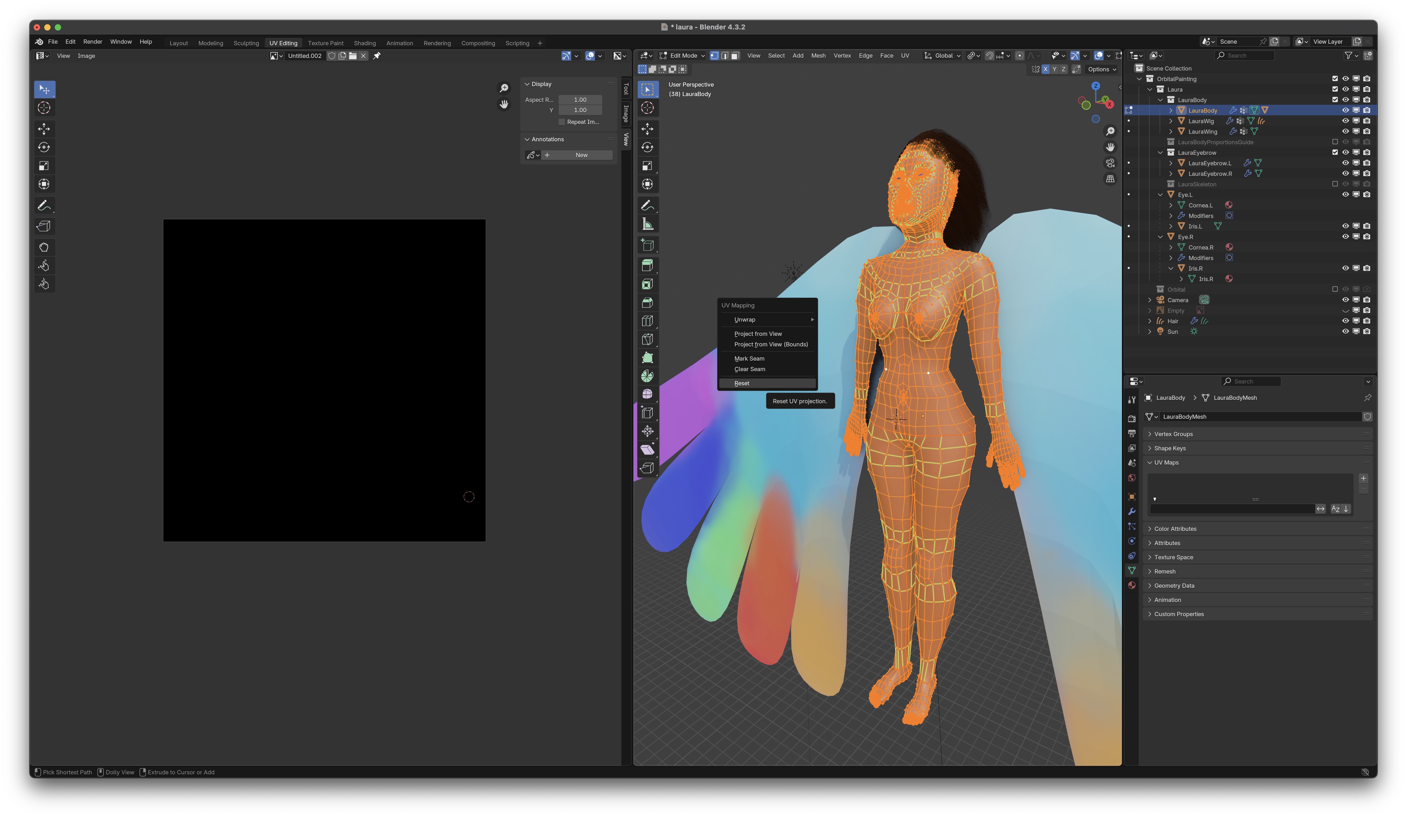
UV Mapping for Head
Reset the mapping
Go to the UV Editing Workspace.
Start clean. In the Properties Editor select Object Data Properties, delete any existing UV maps.
Tab into Edit Mode, selecting the entire mesh with A.
Reset all meshes with U ➤ Reset
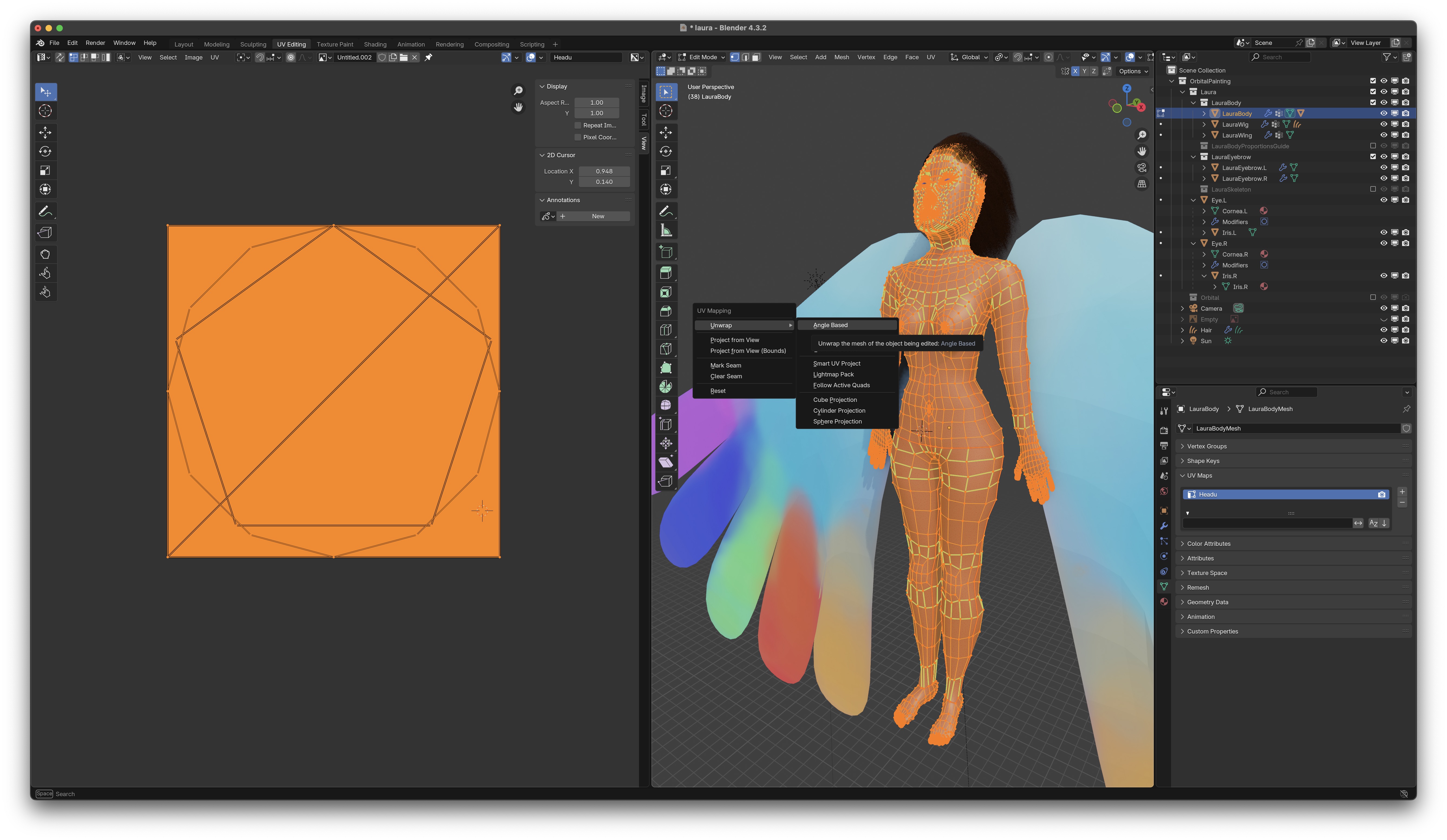
Unwrap the Entire Mesh First
You could select each portion of the entire mesh and unwrap into separate UV mappings. I find it easier to unwrap the entire mesh, and move the unwanted islands outside the image area so they won't be used in the UV map.
In Object Data Properties, double click on the default name UVMap
to rename it to Head
Go into edit mode with Tab.
Select the entire mesh with A, unwrap it with U ➤ Unwrap ➤ Angle Based.
In the left pane you'll see the mesh on a black image grid background (because you don't have an image created for the UV yet).
I already had an old image availble, which is why this image is skin-colored already.
Moving the body islands out of the image, keeping head and ears
Disable Proportional Editing so when you drag the selected mesh outside the image, pieces of the other meshes won't be dragged along as well.
Now we'll move all the mesh pieces outside the image area except the head mesh.
In the left panel, make sure Face Select is enabled. Then click on a face in each of the torso meshes,
use L to select the mesh,
then use translation G to move it outside the image area.
Once you get it out of the way, you can shrink it with scaling S, and arrange using rotation
R.
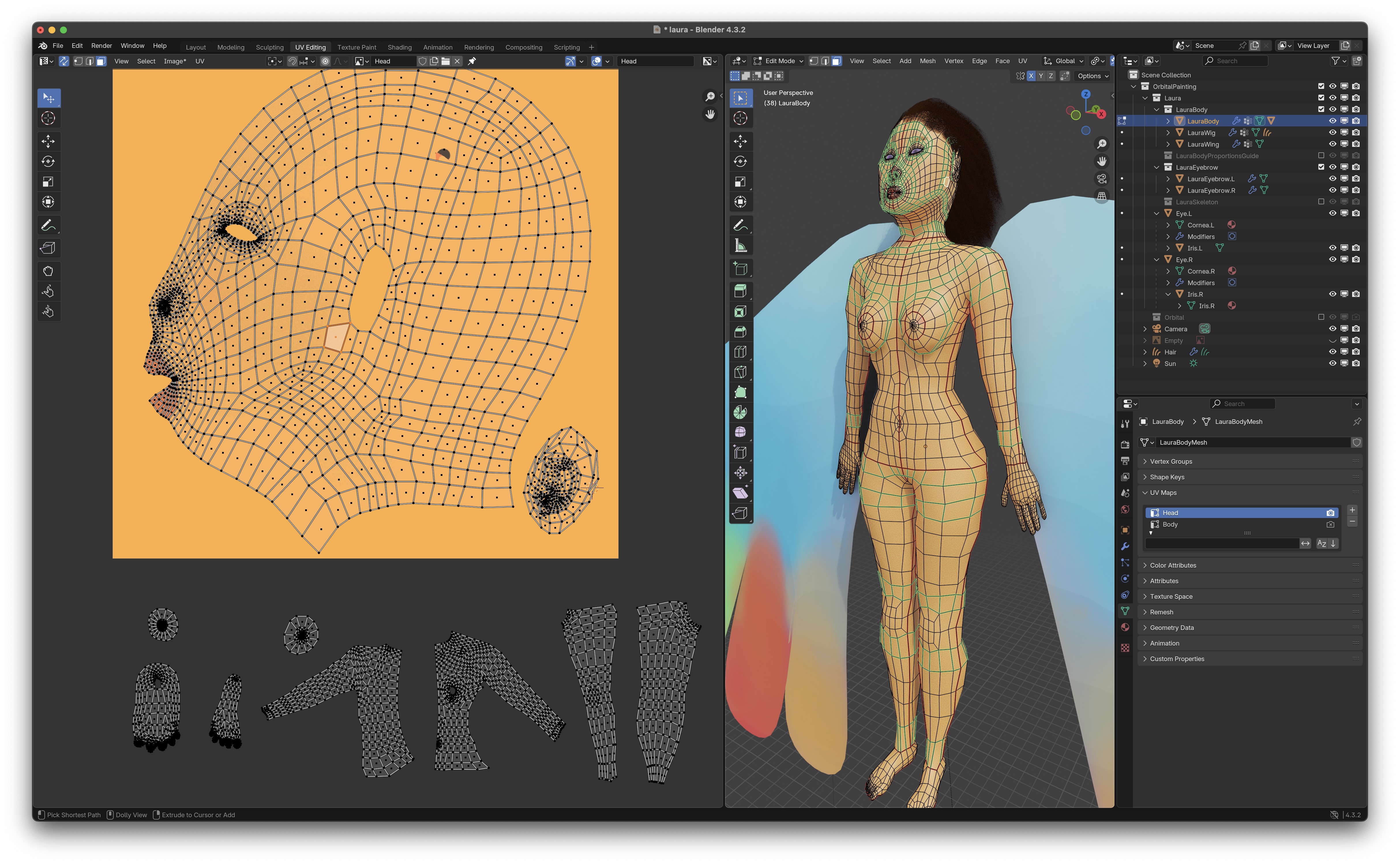
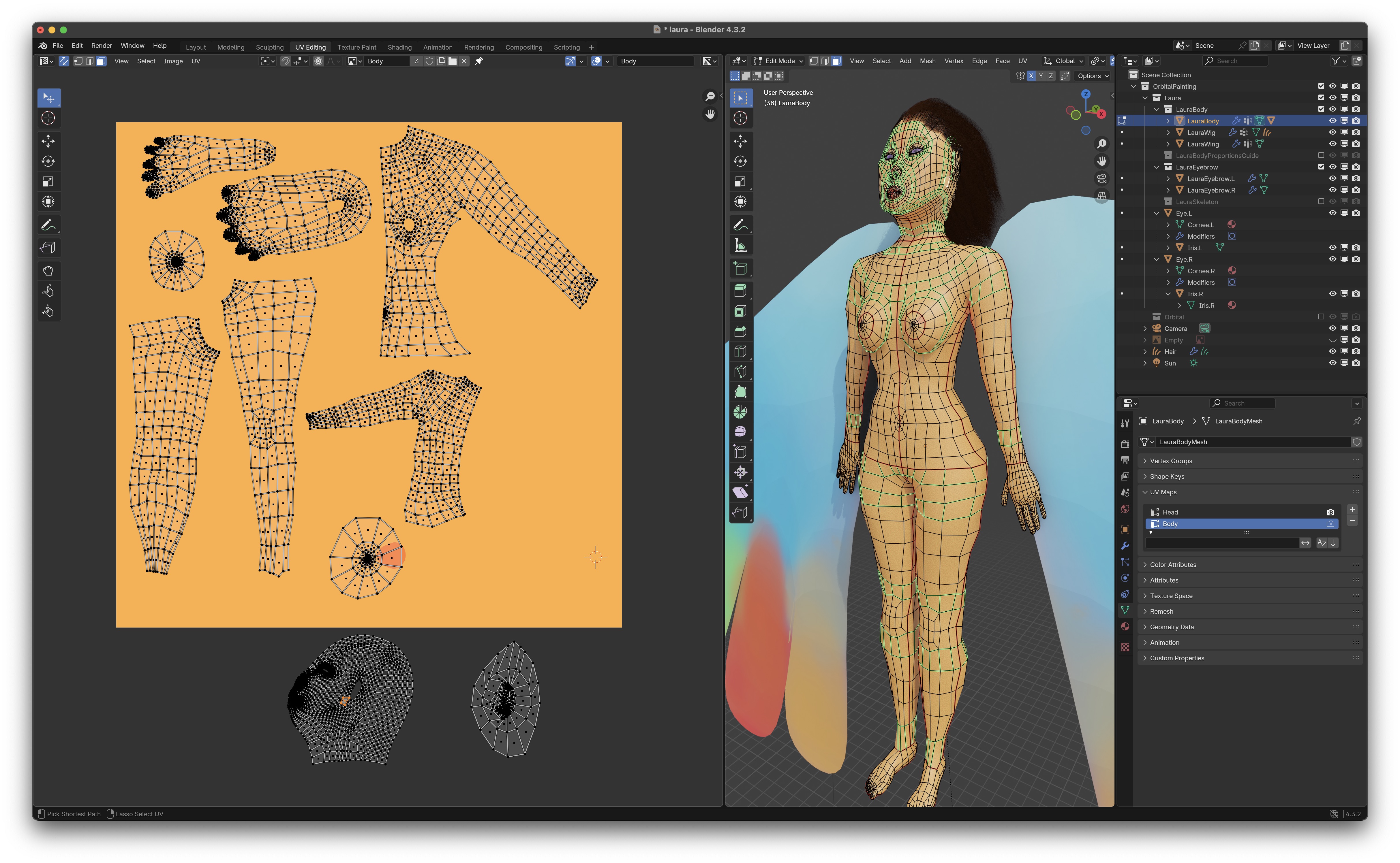
Unwrapping Only the Head Island a Second Time, but With Better Sampling
In the left panel, I clicked on an edge in the head mesh, then selected the entire head using L and then did a second UV unwrap but this time using U ➤ Unwrap ➤ Minimum Stretch which gave me better sampling along the lips and eyes. I did the same for the ear mesh island after moving it back into the image.Creating a New Image
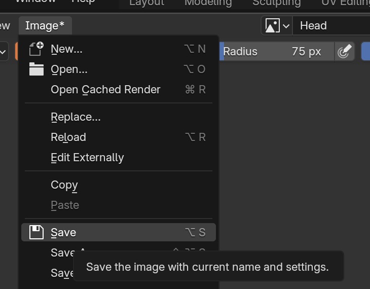
Now create a new UV image for the head mesh using Image ➤ New
We'll use the default resolution of 1024 pixels, and rename to Head
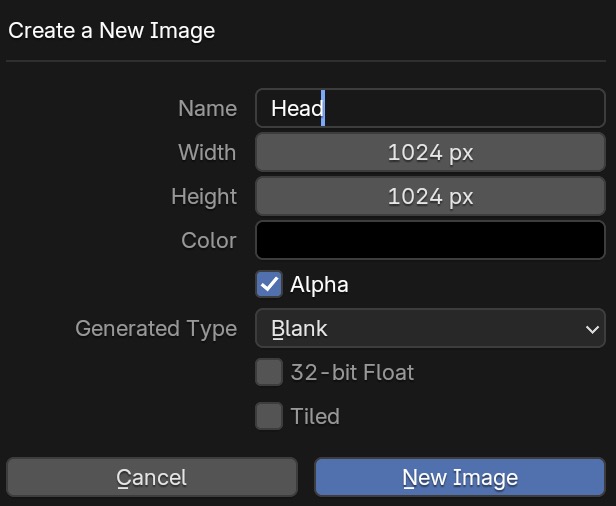 then save it away in the /Textures directory, using Image ➤ Save ➤ Head.png
![]()
Note: Blender won't automatically save your UV images. But it will put a star next to it to remind you to save with Alt S
UV Mapping for Body
Do the same procedure for the body: move the head and ears out of the image, keep the body islands inside the image and
position their sizes and shapes, create an image for the skin, etc.
Skin Color Painting
Now we paint the skin color using texture brushes. Go to the Texture Paint Workspace Let's say you want to work on the Head UV map. To make sure painting on the left image and right model are synchronized, do the following:
-
Select the name of the UV map for the head in the
Properties Panel ➤ Object Data Properties ➤ UV Maps
making sure the camera icon is clicked on:

-
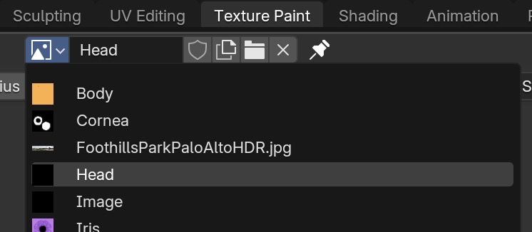
Load the head.png image texture in the left panel.
-
Go to the Shading Workspace. Make sure you've loaded the head.png image as the texture.
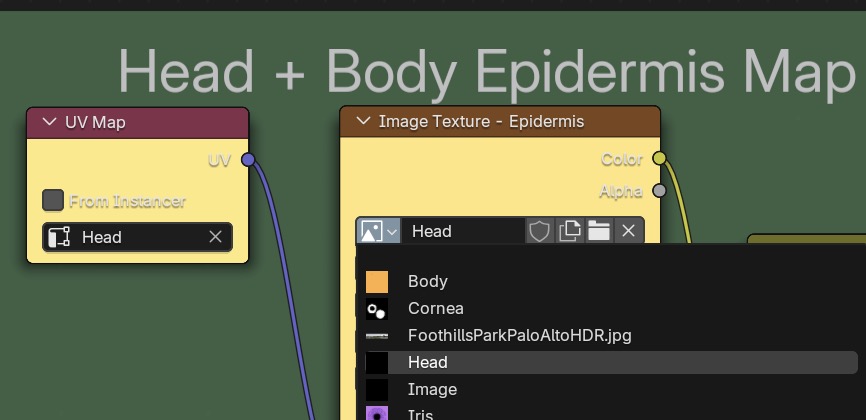
-
You must also click on and select the image texture node for the head.
If you don't, painting on the model won't synchronize with the left panel rectangular texture image display and the colors
will not be correct.
-
Also save the head.png image frequently using Alt S or from the menu.
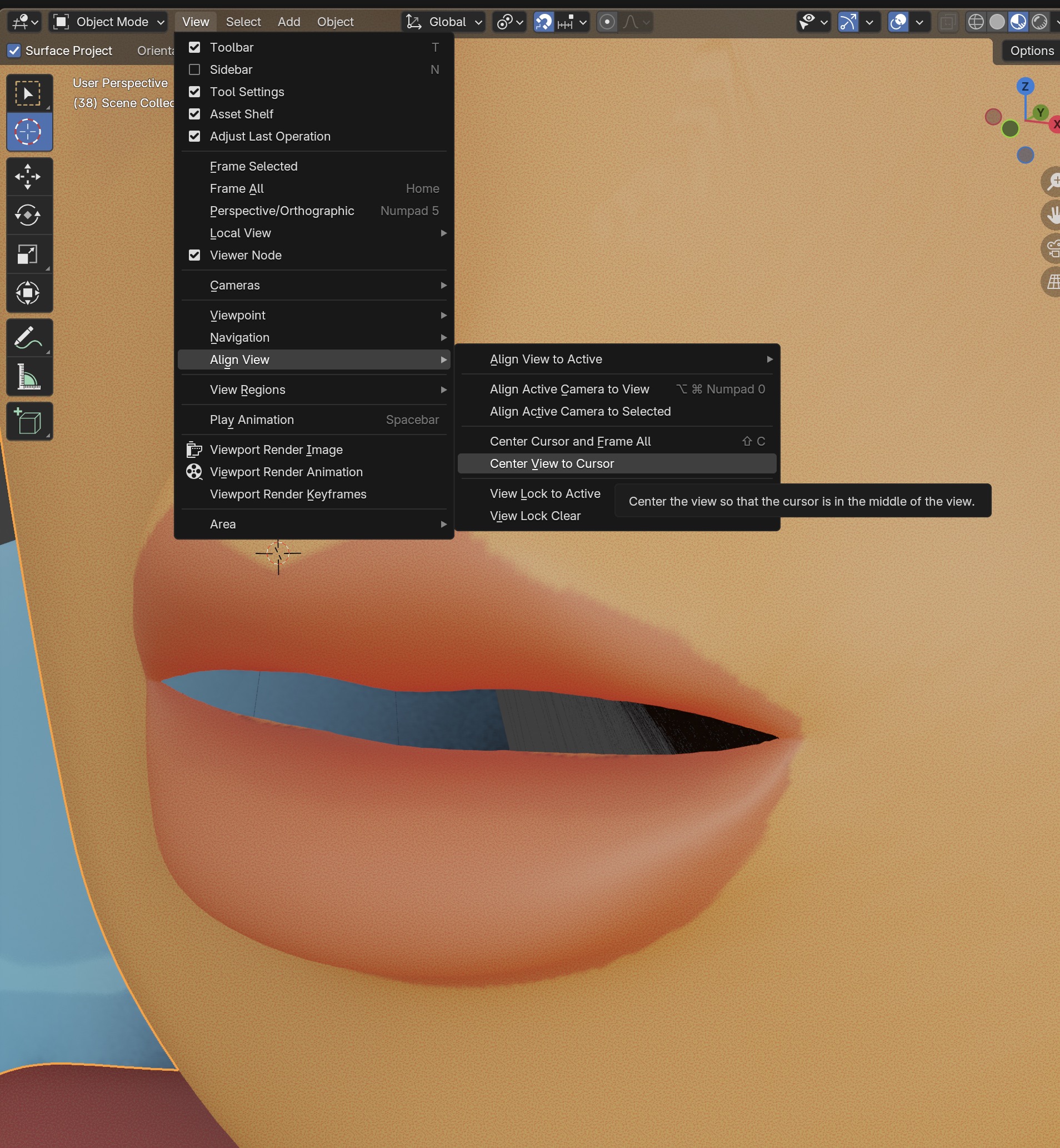
To position yourself for painting the lips in close-up, go into Object Mode in the right panel position the 3D Cursor
over the center of the lips, then View ➤ Align View ➤ Center View to Cursor.
Switch back to Texture Paint mode.
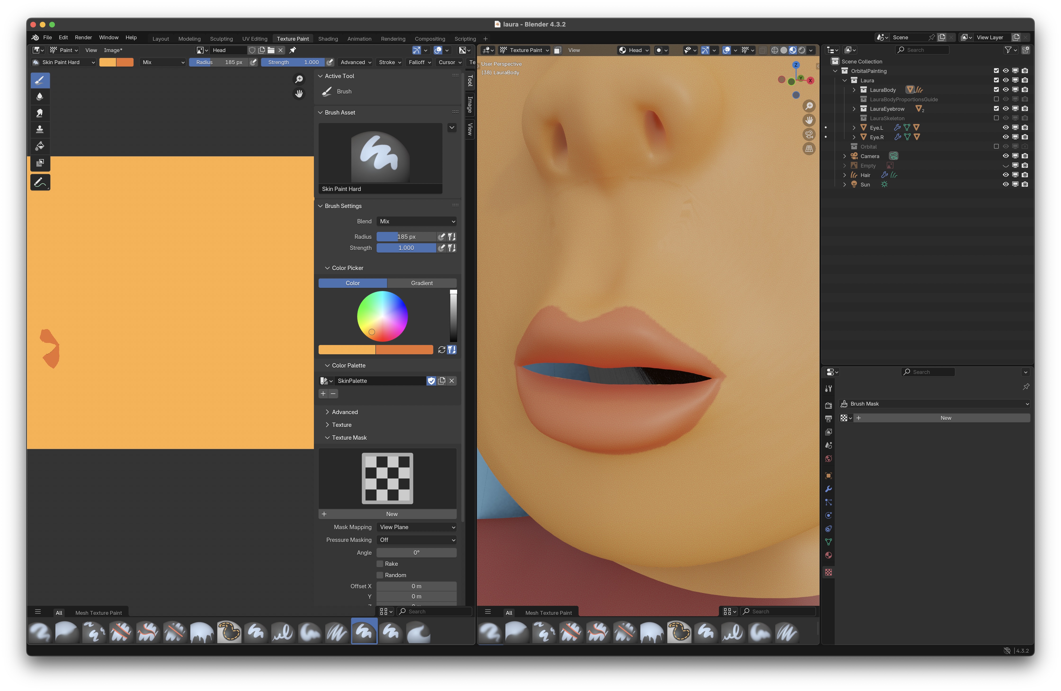
In the Left Panel bring up paint tools with T
and their settings with N.
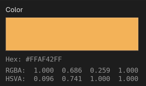
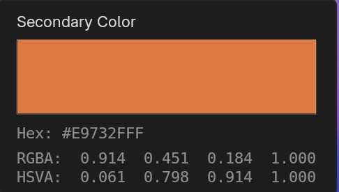
Select a brush type, color, radius, strength and use Mix.
I like to dial down the strength with Shift F and
make several passes to imitiate paintbrush texture.
If your paint brush strokes are grainy in the 3D window with Texture Painting here is the fix:
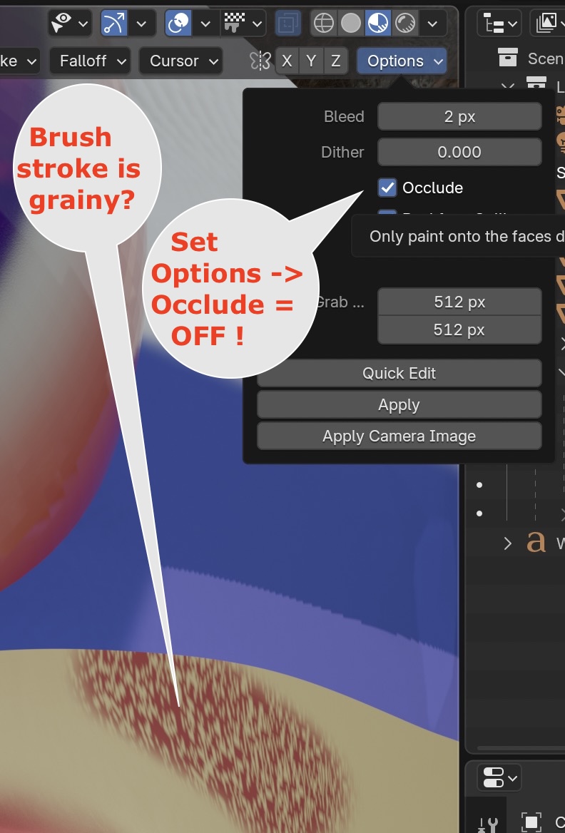
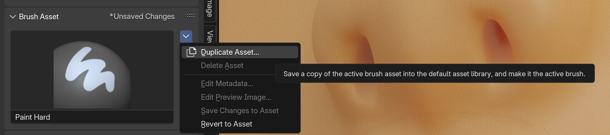
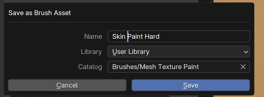
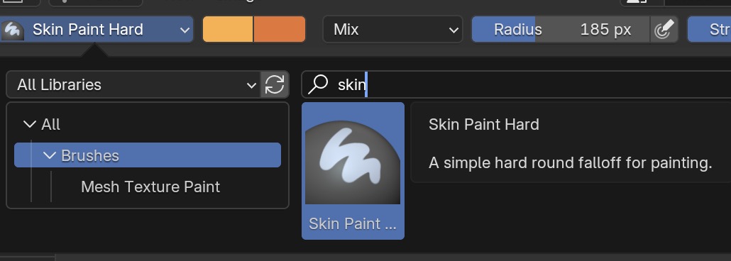
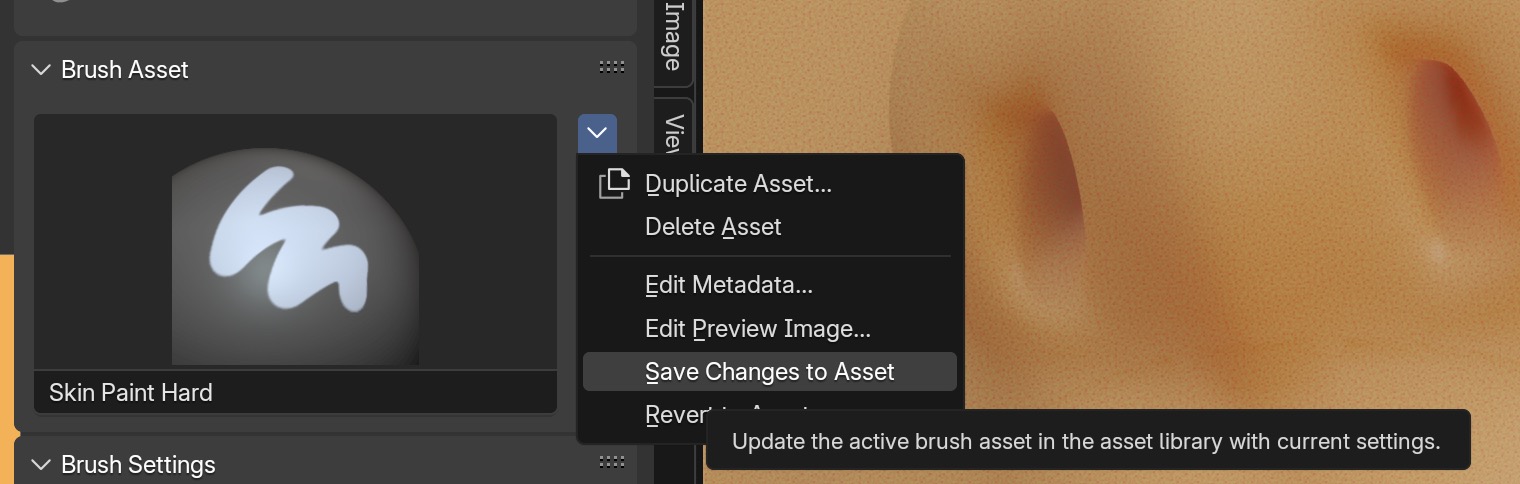
The default brush is painting hard with mix mode. We need to give this brush a name and save it away.
 You can also edit the metadata to document what the brush does.
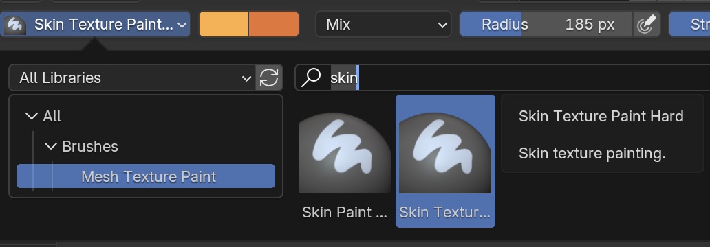
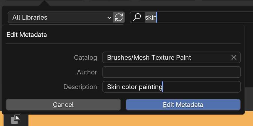 Once saved, you can search for it by name.
Once you have your settings, save them into your brush.
For more realistic skin, we want to paint a texture the solid color.
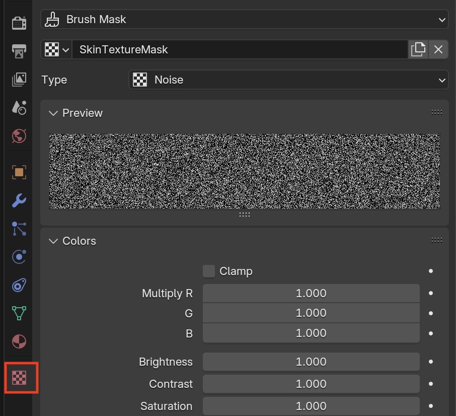
In the left panel, create a new Texture Mask and name it. Then push the toggle which will show the texture map
settings in the right pahel.
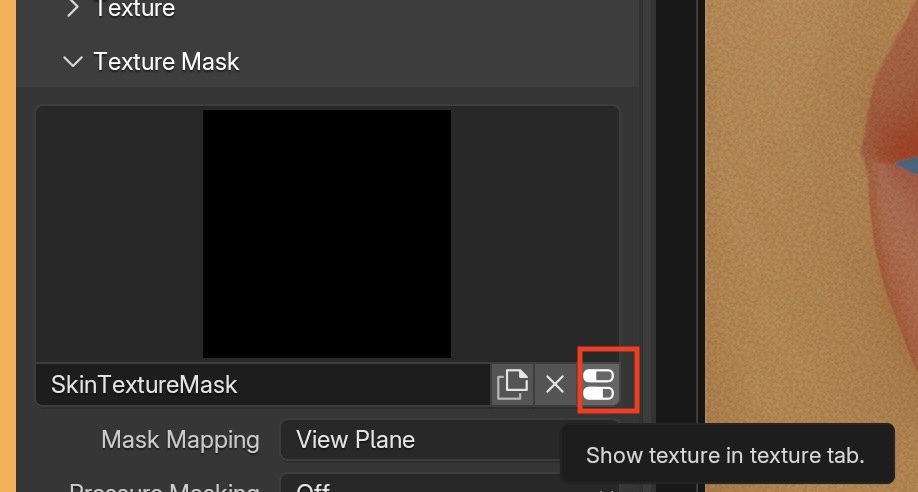
I used a Noise texture to model skin
I experimented and finally used Brush Blending Mode ➤ Darken.
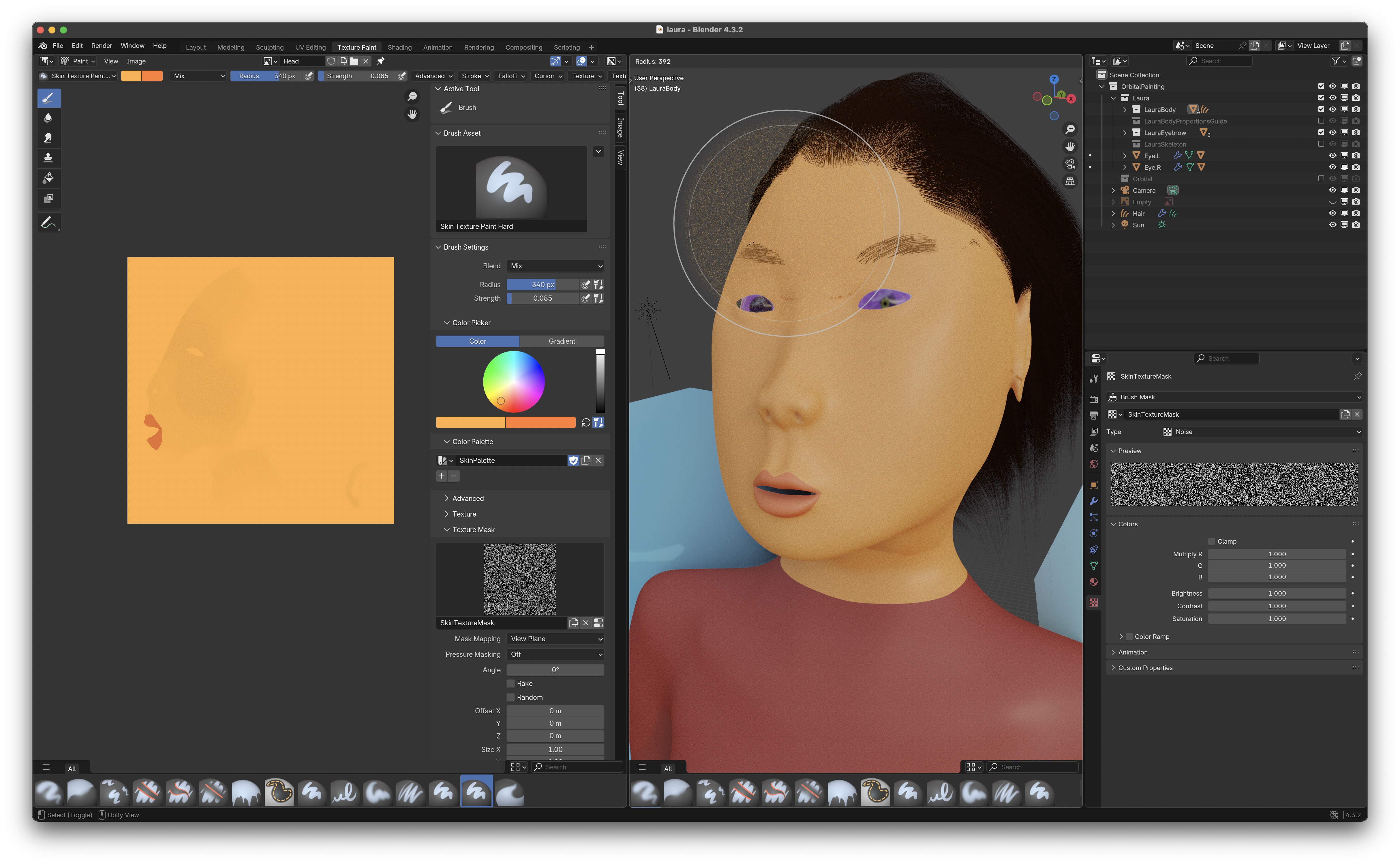
Now I use the brush to paint the texture, selecting a low strength and fairly big size brush. I paint on the model in the right panel
and also on the UV map in the left panel, whichever works better.
Don't don't forget to save the image in the left panel with Alt S.
Duplicate this brush also and save it away as before under a new name. It will show up in your list of brushes.
Now the skin looks less like wax and more like human skin. The lip texture can't be faked with texture painting and is done using normal maps (see below).
Now do the exact same process with the UV map for the torso, starting by creating a new UV map for the torso.
Skin Material Nodes
Go into the Shading Workspace
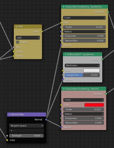
Here are all the material nodes we need for skin. I'll explain in more detail later.
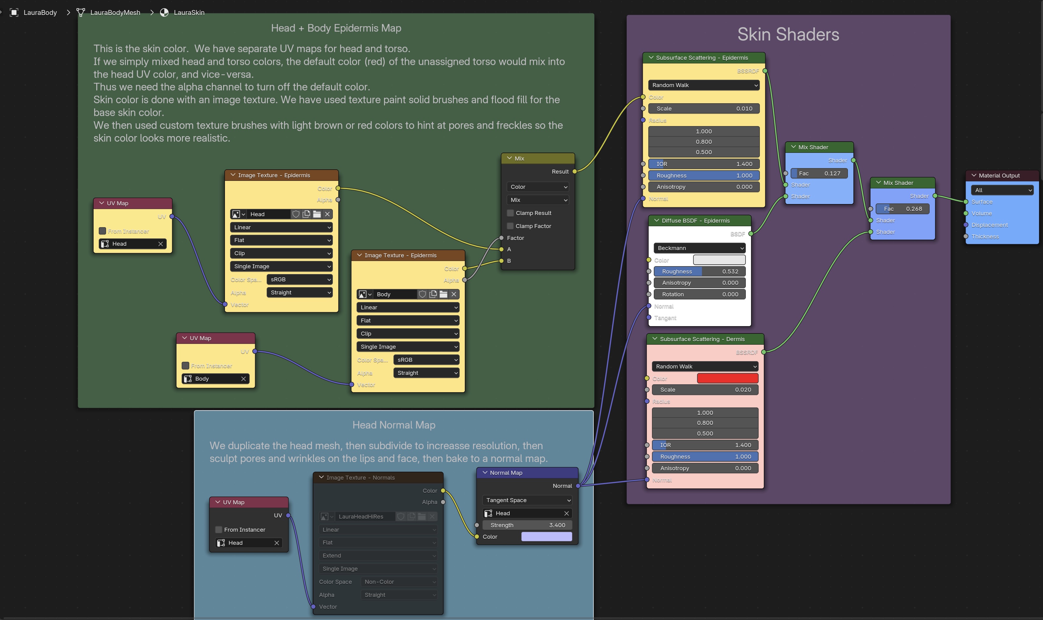
Use Shift A to create the nodes and link their inputs and outputs. Use N to bring up the node properties and change the names and colors of the nodes. To add more text, go to Scripting create a new file, type in text, then name it and save it.
Mostly, I followed people's recommendations: Blender Manual Principled BSDF Shader
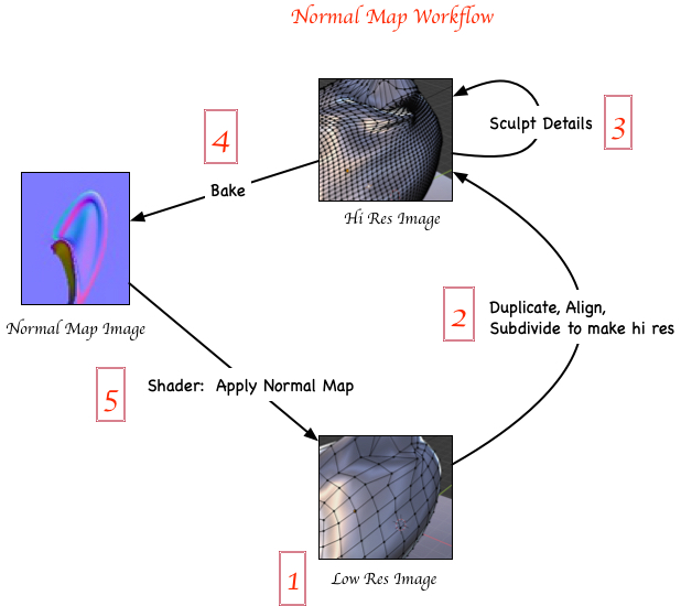
Simulating Pores and Wrinkles with Normal Maps
Texture painting will not be enough for realistic skin. We need to create a high resolution surface and sculpt it with the skin wrinkles. Skin pores are handled differently. We are not going to render a high resolution mesh directly (that would take forever to render). Instead, we'll cheat by mapping the high resolution surface normals to the low resolution mesh to perturb the light paths during rendering and make it appear as if we had the actual high res surface. The process is called texture Baking. Good but not perfect: realism breaks down at sharp viewing angles; in particular the silhouette of the object won't show texture, but will be smooth. Refer to Andrew Price Normal Baking Tutorial. Also see the explanation at One True Guide to Baking Materials in Blender.
Instead of retopologizing a high resolution sculpted mesh to create a low resolution mesh,
I went in the reverse direction by duplicating the low res mesh, and creating a hi res sculpted duplicate.
Creating a Duplicate Hi Res Mesh
In your Modeling Workspace go into edit mode with TAB, then enable
Face Select Mode
Select any vertex on the the head portion of the mesh, say the cheek, and type L to
select all connected parts of the mesh bounded by the UV seams (red edges).
Add other connected parts of the head mesh such as ears to the
selection with SHIFT select on a vertex then L.
 Duplicate the head mesh using SHIFT D, confirm with RETURN, then
separate the mesh with P separate ➤ selection.
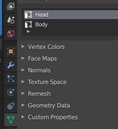
Now the new head mesh will show up as separate item in the
Outliner Panel. It will be displayed on top of the old mesh,
as you can see by toggling Hide/Unhide
Duplicate the head mesh using SHIFT D, confirm with RETURN, then
separate the mesh with P separate ➤ selection.
Now the new head mesh will show up as separate item in the
Outliner Panel. It will be displayed on top of the old mesh,
as you can see by toggling Hide/Unhide
Select the hi res head, then Shift Selectlow res head, then parent it with Ctrl P ➤ Set Parent to Object ➤ (Keep transform) This will anchor it in place. You'll see the Outliner Panel show the parent ➤ child relationship.
In case you have problems later, try this Since the high and low resolution meshes must be aligned perfectly in order to map the normals, get rid of any local transforms by doing Ctrl A ➤ Apply Rotation and Scale to both meshes.
Sculpting the Hi Res Mesh
Go to the Sculpting Workspace and select Sculpt Mode. Shift H to hide all other objects except the hi-res head.
This object will only be used for creating the normal map, so delete the materials in
Material Properties.
Also clear any UV seams and freestyle edges: TAB into edit mode, select the entire mesh with A
and do Ctrl E ➤ Clear Seam, then Ctrl E ➤ Clear Freestyle Edge, then go back into object mode.
The hi res head will appear white now.
 At this point, save a copy of this hi res head by doing Shift D Return then
M to move it to a new collection which you can rename Saved Objects.
Disconnect from the parent using Alt P ➤ Clear Parent
Toggle the filters to turn off its display in viewport and render.
If we mess up the next steps, we can recover using this saved object.
At this point, save a copy of this hi res head by doing Shift D Return then
M to move it to a new collection which you can rename Saved Objects.
Disconnect from the parent using Alt P ➤ Clear Parent
Toggle the filters to turn off its display in viewport and render.
If we mess up the next steps, we can recover using this saved object.
Apply the mirror modifier (which is irreversible, which is why we made a copy of the head),
and also apply the subsurf modifier. At this point, go into edit mode to check the mesh resolution.
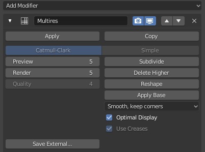
If it is not fine enough to support sculping fine detail, select
Add Modifier ➤ Generate ➤ Multiresolution.
Subdivide 2 or more times to get fine enough
resolution for the lips when sculpting, and hit Apply to make the subdivisions permanent and
remove the Multiresolution modifier from the modifier stack. You can always Ctrl-Z to undo if you have subdivided too much or too little.
If you enable Edit Mode you can see just how fine the mesh is:
Go into the Sculpting Workspace and select Sculpt Mode.
Turn off the X-mirror property so you can draw without duplicating your brush strokes in the x-direction.
Select T to bring up the brushes if they are not already present.
Select the Draw Brush
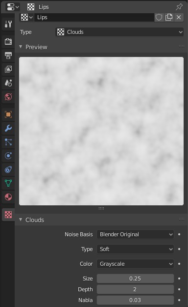
Under Texture, create a new texture for the brush.
Over in the Properties Panel ➤ Texture Properties,
select a noise texture of type Clouds
 Adjust the brush radius with F and the mouse.
Brush strength is Shift F.
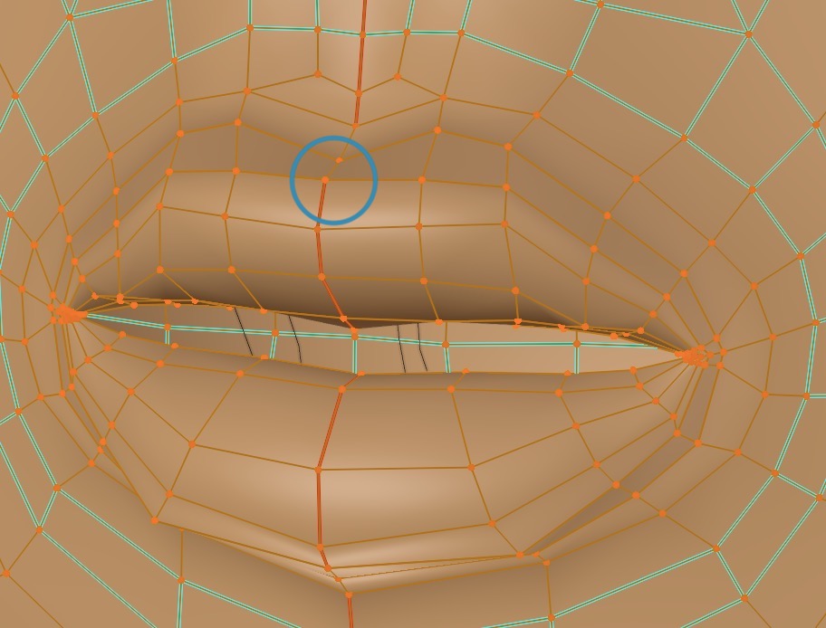
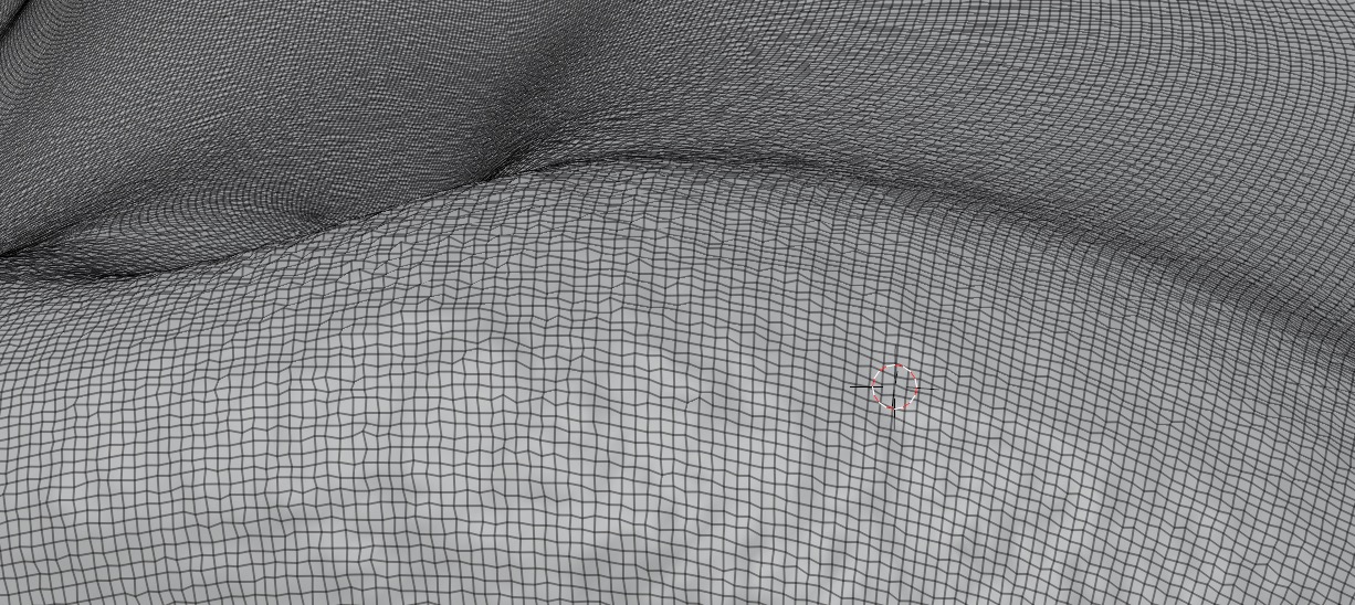
Sculpt the high res mesh for the head in the area of the lips,
Adjust the brush radius with F and the mouse.
Brush strength is Shift F.
Sculpt the high res mesh for the head in the area of the lips,
Baking Normals for Skin Coarse Texture
This has several steps.Creating the Normal Map Nodes
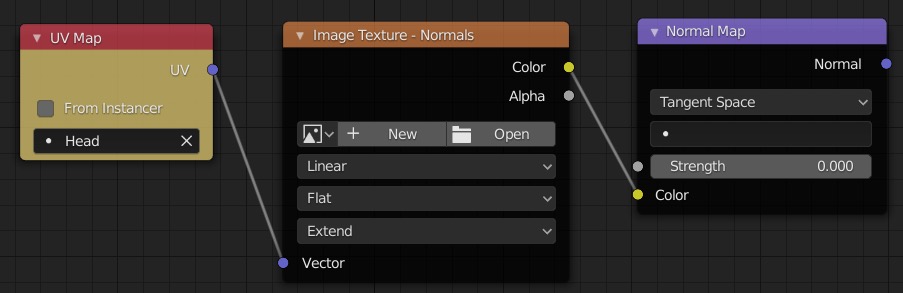
Create three new nodes for the normal map in the compositing window with Shift A.
- In the UV Map node, select the low res head mesh; normal baking needs to know the coordinate system.
- We'll create the image texture later.
- Use Tangent Space and leave the Strength later. Don't connect the output yet --- if you do, you'll get a "circular dependency" warning later when baking. If you insist, you can connect the outputs but simply ignore the warning.
Baking assumes we have a UV map for the low res mesh already in place, and we do.
But since we have multiple UV maps, we will need to explicitly select the UV Map for head to be active.
Do that in the
Outliner ➤ Object Data Properties,
 Also you need to make visible the layers containing both hi res and low res meshes (or you'll get a warning).
Create a Blank Hi Res Normal Map Image
Go to the UV Editing Workspace.
In the in the left pane create a new hi res normal image texture, 4096 x 4096, which is defaulted to black.
You can do math inside Blender's input fields such as typing * 4 in the input field.
You can drag downwards to copy the value to other fields.
Give it a name also, "LauraHeadHiRes"
![]()
![]()
![]()
![]() It's important to have the normal map image loaded in the Image Texture - Normals node and the left pane of the UV Editor show the
corresponding same name for the active normal map image to avoid getting a warning.
It's important to have the normal map image loaded in the Image Texture - Normals node and the left pane of the UV Editor show the
corresponding same name for the active normal map image to avoid getting a warning.
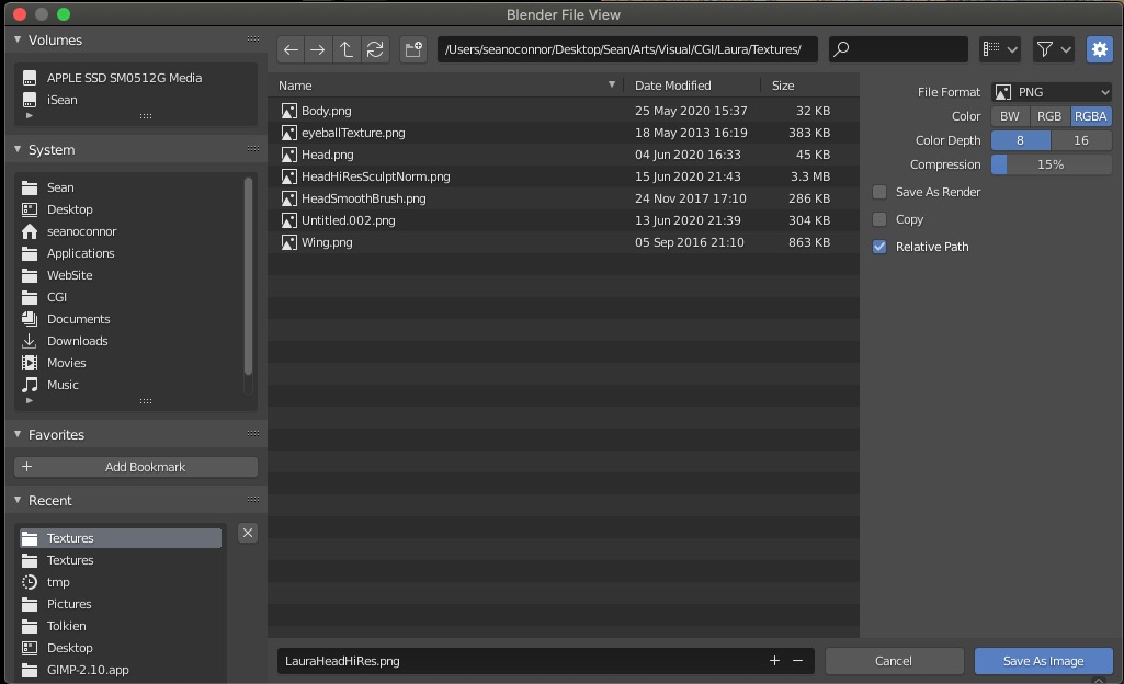
Hit Alt S to bring up a dialog window, then rename and save the blank image to the /textures folder,
 Now go to the Shading Workspace.
Select the normal texture node and open the blank texture image you've just created,
Now go to the Shading Workspace.
Select the normal texture node and open the blank texture image you've just created,
![]() Select Non-color Data because it's color coded normal vectors components.
Extend paints normals of zero beyond the normal map image applied to the head.
A bit of trial and error here to avoid the normal map being applied to the rest of the body.
Select Non-color Data because it's color coded normal vectors components.
Extend paints normals of zero beyond the normal map image applied to the head.
A bit of trial and error here to avoid the normal map being applied to the rest of the body.
Baking: Hi Res Mesh ➤ Normal Map Image
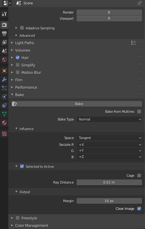
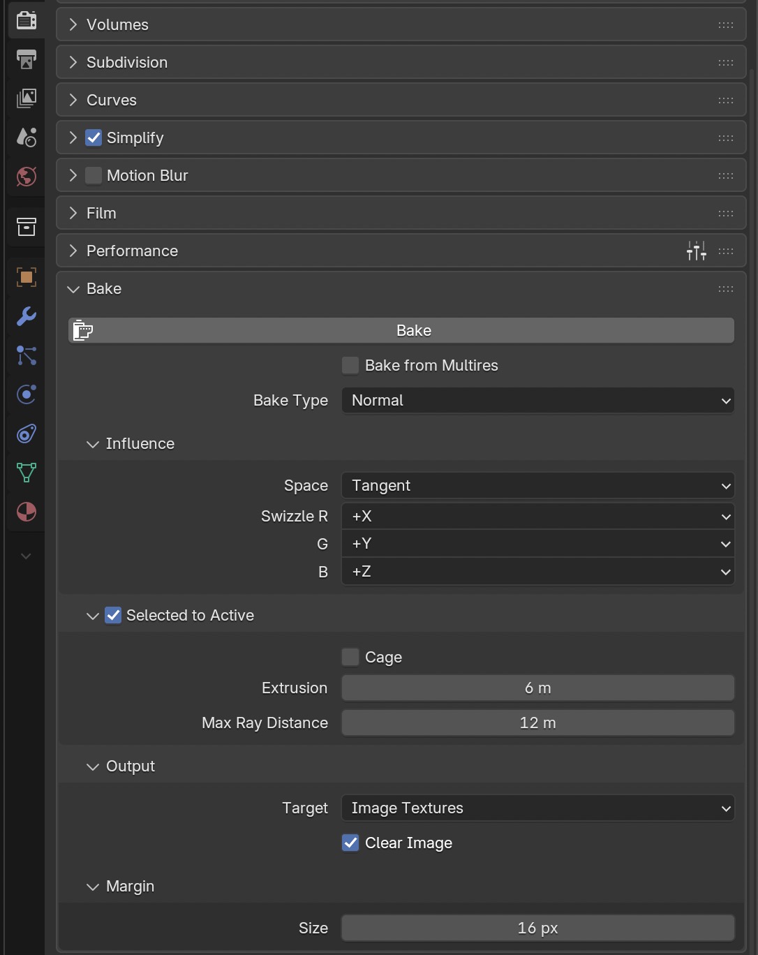
In Render Properties ➤ Bake select Bake Type ➤ Normal, Influence ➤ Space ➤ Tangent, Selected to Active.
During baking, rays are cast from the low-res mesh to the high-res mesh.
This assumes the high-res mesh is contained inside the low-res mesh.
Since this won't normally be the case, the Extrusion parameter moves the low-res mesh outwards
until this condition holds. I assume your texture is not too extreme, so you can try 1cm to begin with.
You'll want to limit the Max Ray Distance to about 2x the extrusion.
If you don't, rays may intercept distant geometry and you'll get a normal map appearing far outside your mesh.
In the 3D viewport panel at the right, first select the hi res head, and keeping the mouse in the same spot, shift select the low res head (must be in that order!). The active object is the one last selected. You can look at the outliner panel to confirm the order of the selections are correct by seeing an orange color for the hi res head and a yellow color for the low res head.
Make sure your texture image node is selected and is named to the blank image created above. Baking's default output goes to the active texture image node file.
Now hit the Bake button in the render
panel. This will take a few minutes.
Once baking finishes, in the image editor window, hit Alt S to save the image
(Blender save won't automatically save your images).
You may see Blender remind you to do the saving right after the bake finishes.
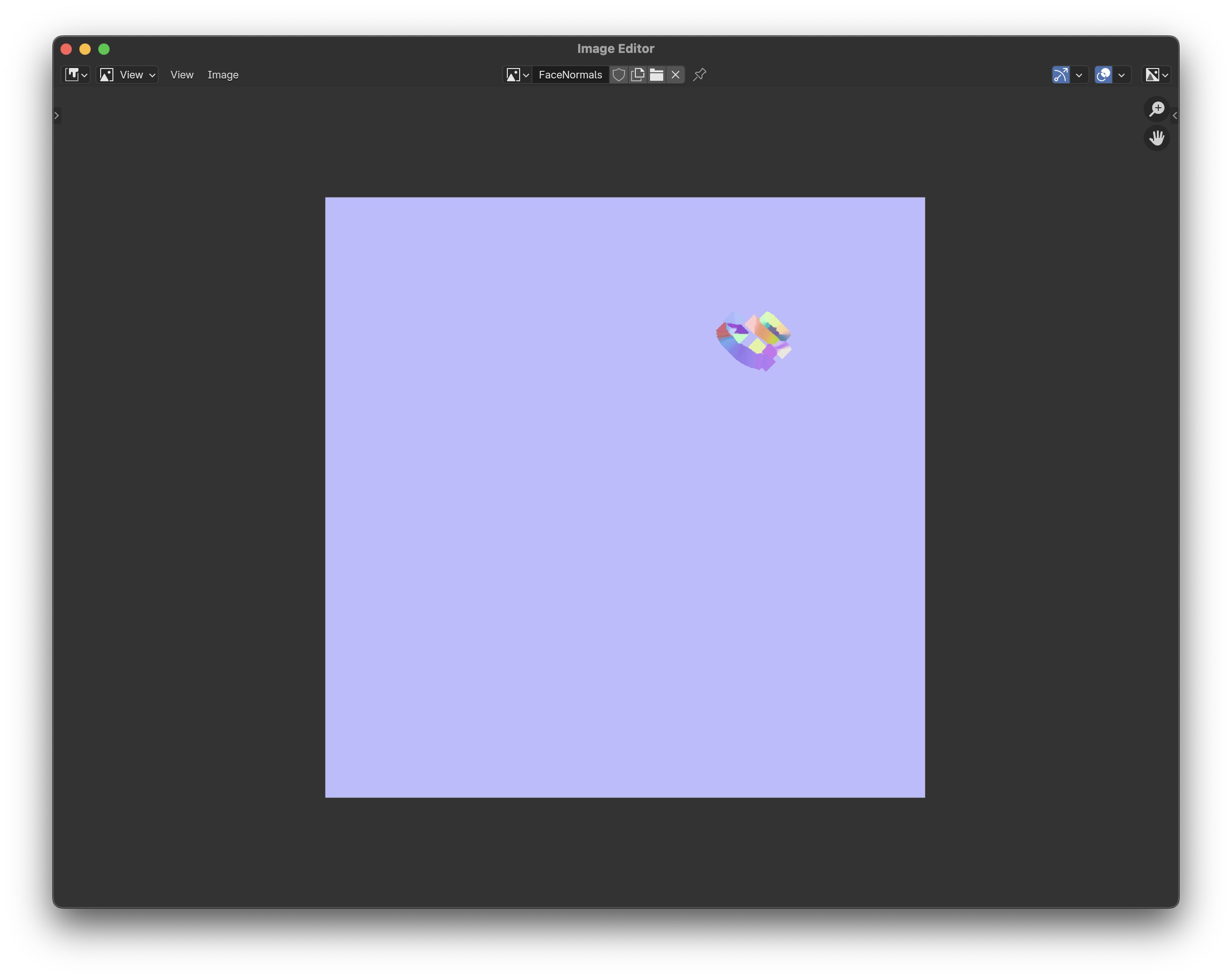
Here is the normal map image:
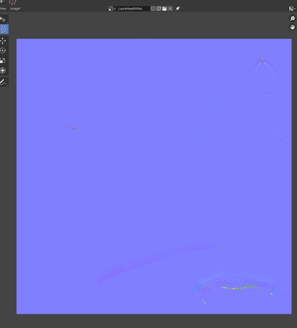
Normals pointing straight up from a flat surface show up as blue; this is your background color. See mathematics of normals for the normal vector mathematics and color interpretation.
Troubleshooting: If you just see a completely blank blueish image after baking and yet no error messages...
- Check that your objects have UV maps, i.e. you've reset and unwrapped vertices in the UV editor, and named the UV map.
- Meshes must be aligned perfectly in order to map the normals, get rid of any local transforms by doing Ctrl A ➤ Apply Rotation and Scale to both meshes. You'll need to select both meshes!
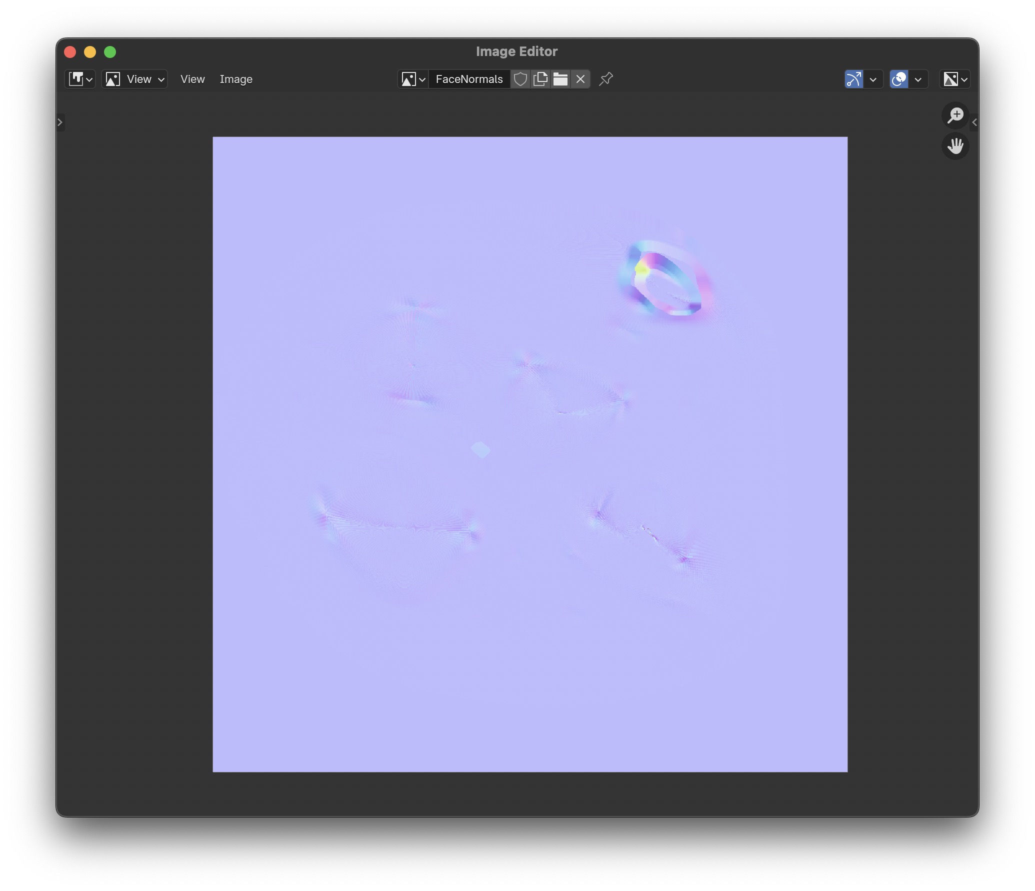
You will probably have to iterate, so open a new active workspace as an Image Editor window. Select the name of the normal map. After baking the image, you should see fine textured purples, blue and pink, but not large mustard green and red blotches, and no black holes. If not, you need to adjust the extrusion and ray distance parameters, and possibly reduce the size of the texture. If you still get artifacts in the normal image, one workaround is to use Gimp, to paint them out using a clone brush set to the background color (zero normals). and resave the image.
Go back to the Shading Workspace.
Reconnect the normal output to the shader nodes inputs,
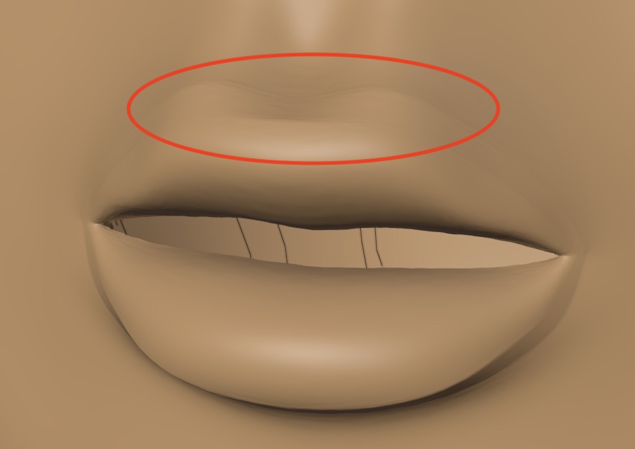
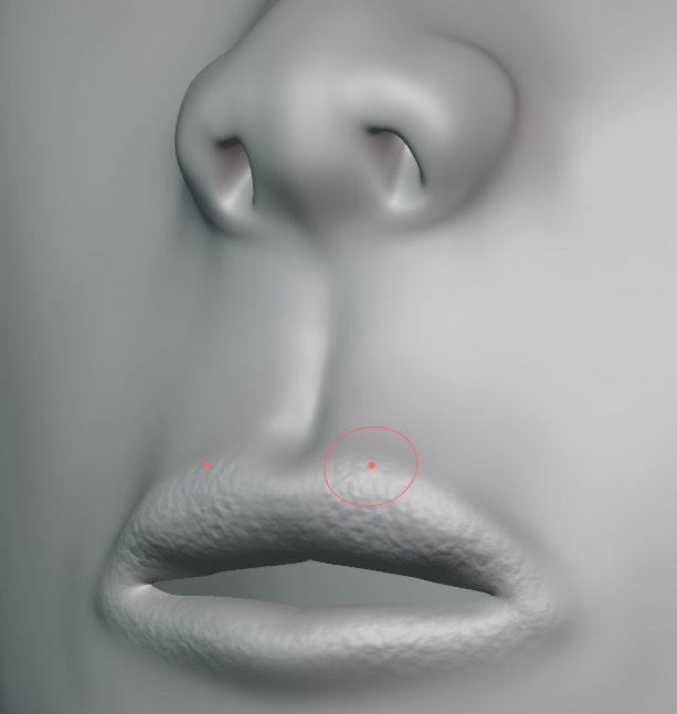
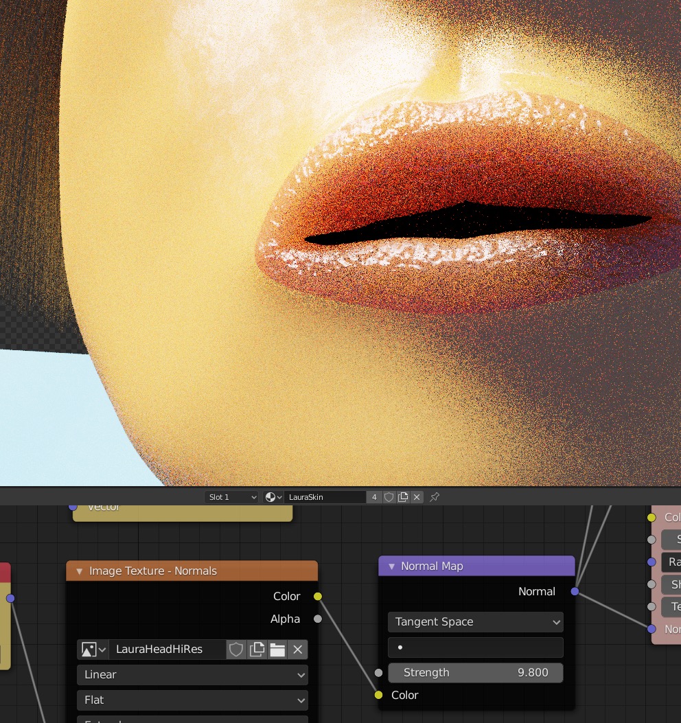
Tweaking the Normal Map Strength
Hide the hi res image with H.
Switch into render mode and adjust the Strength up from zero while rendering. I finally used a strength of
3.3 to show the roughness of the lips but not cause artifacts in the rest of the face.
Skin Pores
It would take too much computation to create skin pores by baking a hi res sculpted mesh to a normal map image. Instead we do this:
- Create a pair of small mesh planes with high resolution.
- Sculpt human skin pores, which are about are about $250\mu \text{to} 500\mu$, on the plane.
- Bake to a normal map image.
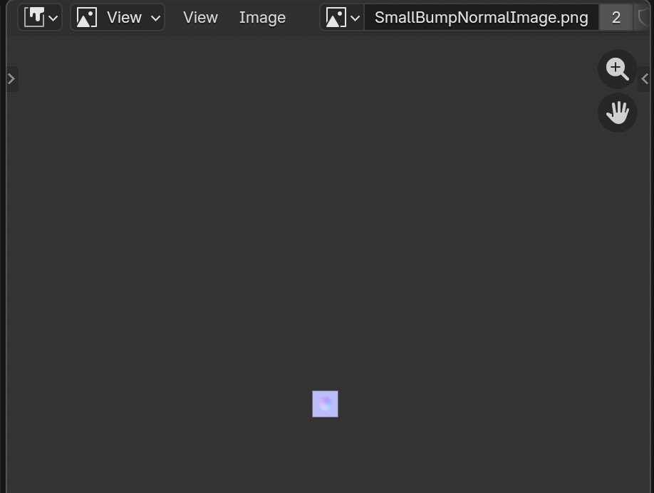
- Use an image scaling node to tile copies of this small normal image over the entire object. Make sure pores are positioned randomly enough at the edges so tiling won't show seams.
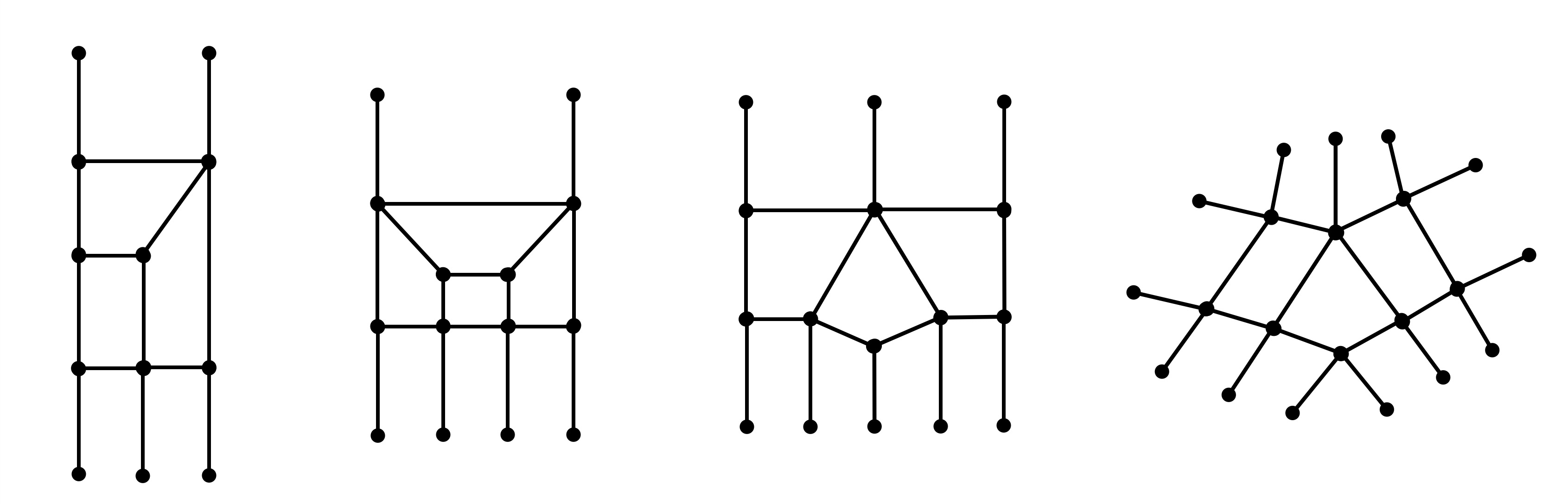
Simple Example for Reoriented Normal Mapping (RNM) Method
I've used the following references: how to combine two normal maps with the Reoriented Normal Mapping (RNM) method. with an example showing shading for RNM. Here is a tutorial on quaternions which also describes their rotation properties. The Blender node group for RNM is from stack exchange Blender Stack exchange: combine two normal maps
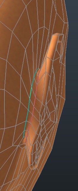
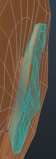
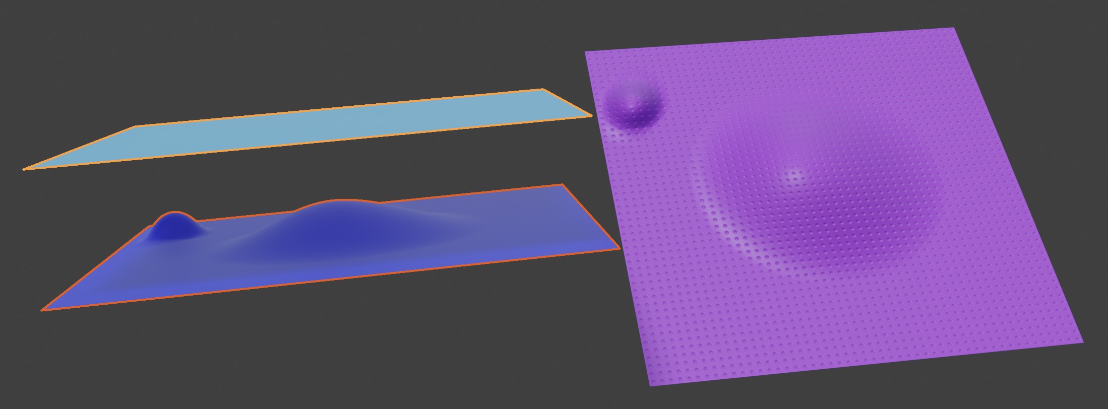
We create three plane meshes.
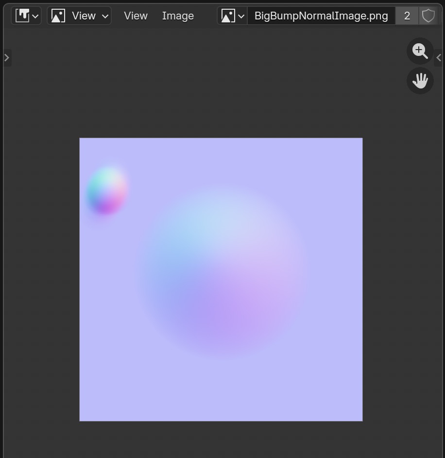
We subdivide a plane mesh to make it high resolution, then sculpt bumps on it (dark blue).
We create two simple plane meshes with no subdivisions (light blue and purple).
Light blue is the low res target mesh for the baking of the large sculpted bump.
Purple is the result of combining two normal maps, one for the large bump and another for a small bump which is repeatedly tiled.
When baking, you select the dark blue mesh first (orange line), then the light blue mesh (yellow line),
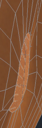
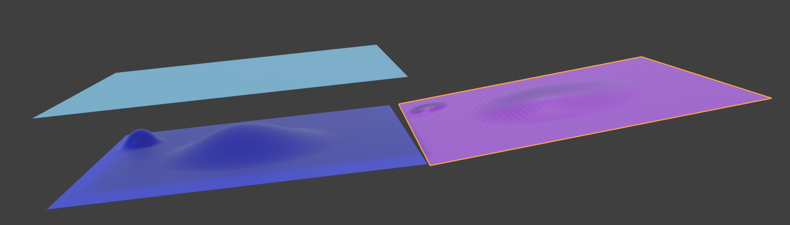
 You can see the normal map isn't really deforming the surface, but simulates it by altering light rays,
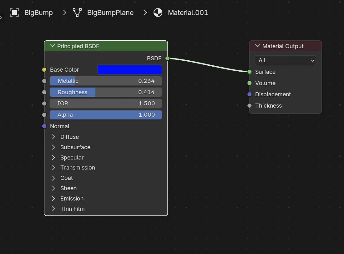
 The dark blue mesh has only a simple material.
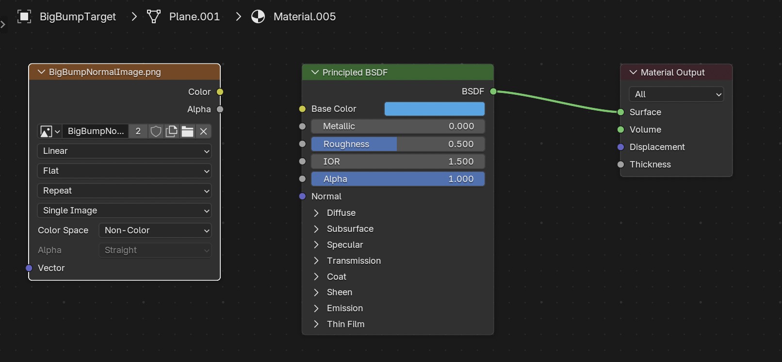
 The light blue mesh as an image texture node, which we select so that it gets the normal image as a target when we bake.
 Here are the bake settings,
 We get this normal map image,
 We then use GIMP to scale down the image size to make it tiny,
 These are the nodes for the purple mesh,
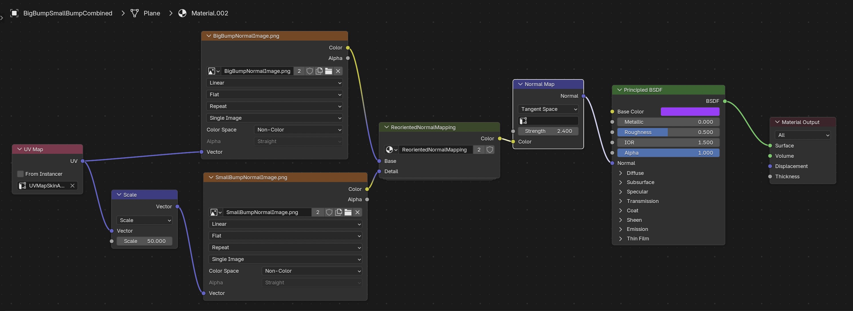 and the normal map mixing nodes,
Mathematics of RNM Method
The RNM method uses the mathematics of quaternions and their rotation properties. Here's all the mathematics in one place, for your convenience.
Preliminaries: Vector Cross Products, Dot Products, Trig identities
Proposition Pythagorean circle identity $$ \sin^2 \theta + \cos^2 \theta = 1 $$
Proposition Cosine half angle formula $$ \cos \frac{ \theta}{2} = \sqrt{ \frac{ 1 + \cos \theta}{2}} $$ Proof From ways to prove the half angle formulas for sine and cosine using Euler's formula $e^{i \theta} = cos \theta + i sin \theta$, $$ e^{i 2 \theta} = cos( 2 \theta ) + i sin( 2 \theta ) = e^{i \theta} \: e^{i \theta} = (cos \theta + i sin \theta ) (cos \theta + i sin \theta) = (cos^2 \theta - sin^2 \theta) + i (2 sin \theta cos \theta ) $$ Equating real parts, and using the Pythagorean circle identity, $$ cos 2 \theta = cos^2 \theta - sin^2 \theta = 2 cos^2 \theta - 1 $$ $$ \implies cos \theta = \sqrt{ \frac{ cos 2 \theta + 1 }{2} } $$ Then replace $\theta \rightarrow \theta / 2$ $\blacksquare$
Proposition Sine half angle formula $$ \sin \frac{ \theta }{ 2 } = \sqrt{ \frac{ 1 - \cos \theta}{2} } $$
Consider the vectors $\mathbf{ A } = (a_2, a_3, a_4)$ and $\mathbf{ B } = (b_2, b_3, b_4)$ $A, B \in \mathbb{ R }^3$ You'll see the reasoning for the indices later.
Definition. Vector cross product is most easily remembered as the formal determinant, $$ \mathbf{A \times B} = \left| \begin{array}{lll} \mathbf{ \hat{i}} & \mathbf{\hat{j}} & \mathbf{\hat{k}} \\ a_2 & a_3 & a_4 \\ b_2 & b_3 & b_4 \end{array} \right| = \left( \begin{array}{l} a_3 b_4 - a_4 b_3 \\ a_4 b_2 - a_2 b_4 \\ a_2 b_3 - a_3 b_2 \end{array} \right) $$
Definition. Vector dot product. $$ \mathbf{A \cdot B} = a_2 b_2 + a_3 b_3 + a_4 b_4 $$
Lemma. Dot product formula. $\mathbf{A \cdot B} = \lVert \mathbf{A} \rVert \lVert \mathbf{B} \rVert \: cos \theta$
Proof Expand out ${\lVert \mathbf{ A - B } \rVert}^2$ as a dot product. Then write the law of cosines on all vector norms, and equate the two expressions. (Recall the law of cosines for triangle ABC with sides abc states $c^2 = a^2 + b^2 - 2 a b \cos C$, generalizing the Pythagorean theorem.) $\blacksquare$
Lemma. Lagrange's Identity ${\lVert \mathbf{ A \times B } \rVert}^2 = {\lVert \mathbf{A} \rVert}^2 {\lVert \mathbf{B} \rVert}^2 - \left( \mathbf{ A \cdot B } \right)^2$
Proof. By multiplying out all the terms and comparing. $\blacksquare$
Proposition Cross product formula.
$$\lVert \mathbf{A \times B} \rVert = \lVert \mathbf{A} \rVert \lVert \mathbf{B} \rVert \: sin \: \theta$$
Proof. Use Lagrange's identity and the dot product formula. $\blacksquare$
Proposition Cross product identity. $$\mathbf{ A } \cdot (\mathbf{ A } \times \mathbf{ B } ) = 0$$ Proof. Multiply out all terms to find they all cancel. Or note that the cross product ($\mathbf{ A } \times \mathbf{ B }) \perp \mathbf{ A }$ $\blacksquare$
Proposition Cross product identity. $$ \mathbf{ A } \times \mathbf{ B } = -\mathbf{ B } \times \mathbf{ A } $$ Proof. Multiply out all terms. Or usie the right hand rule in the definition of cross product to see the vector direction is inverted (negative). $\blacksquare$
Proposition Vector triple product $$ \mathbf{ A } \times (\mathbf{ B } \times \mathbf{ C } ) = (\mathbf{ A } \cdot \mathbf{ C }) \mathbf{ B } - (\mathbf{ A } \cdot \mathbf{ B }) \mathbf{ C } $$ Proof $$ \mathbf{A \times (B \times C)} = \left( \begin{array}{lll} \mathbf{\hat{i}} & \mathbf{\hat{j}} & \mathbf{\hat{k}} \\ a_2 & a_3 & a_4 \\ b_3 c_4 - b_4 c_3 & b_4 c_2 - b_2 c_4 & b_2 c_3 - b_3 c_2 \end{array} \right) $$
The $i^{th}$ term is $$a_3 b_2 c_3 - a_3 b_3 c_2 - a_4 b_4 c_2 + a_4 b_2 c_4$$ $$+ a_2 b_2 c_2 - a_2 b_2 c_2$$
which is the same as the $i^{th}$ term of $(\mathbf{ A } \cdot \mathbf{ C }) \mathbf{ B } - (\mathbf{ A } \cdot \mathbf{ B }) \mathbf{ C }$ $$a_2 b_2 c_2 + a_3 b_2 c_3 + a_4 b_2 c_4 - a_2 b_2 c_2 - a_3 b_3 c_2 - a_4 b_4 c_2$$ Similarly for $j^{th}$ and $k^{th}$ terms! $\blacksquare$
Quaternions - Basics
Definition. Quaternions are a division ring which extend the complex numbers. Complex numbers can do rotations in two dimensions, but quaternions can do rotations in three dimensions. We extend the real numbers with three new symbols $\mathbf{i}, \mathbf{j}, \mathbf{k}$ having the rules $$\mathbf{i}^2 = \mathbf{j}^2 = \mathbf{k}^2 = -1$$ $$\mathbf{i j} = -\mathbf{j i} = \mathbf{k}$$ $$\mathbf{j k} = -\mathbf{k j} = \mathbf{i}$$ $$\mathbf{k i} = -\mathbf{i k} = \mathbf{j}$$ Quaternions are written as $$\mathbf{a} = a_1 + a_2 \mathbf{i} + a_3 \mathbf{j} + a_4 \mathbf{k}$$ $$\mathbf{b} = b_1 + b_2 \mathbf{i} + b_3 \mathbf{j} + b_4 \mathbf{k}$$ where $a_i$ are real numbers. Note multiplication is not commutative. A good textbook reference is Topics in Algebra, 2nd Edition 2nd Edition by I. N. Herstein An article which also describes the basics is Quaternions, Interpolation and Animation by E B Dam, M Koch and M Lillholm
We can write quaternions in scalar and vector notation, $$\mathbf{a} = [s_a, \: \mathbf{v_a}] \: \text{where} \: s_a = a_1 \: \text{and} \: \mathbf{v_a} = (a_2, a_3, a_4)$$ $$\mathbf{b} = [s_b, \: \mathbf{v_b}] \: \text{where} \: s_b = b_1 \: \text{and} \: \mathbf{v_b} = (b_2, b_3, b_4)$$ Definition. The sum of two quaternions is $$\mathbf{a + b} = (a_1 + b_1) + (a_2 + b_2) \mathbf{i} + (a_3 + b_3) \mathbf{j} + (a_4 + b_4) \mathbf{k}$$ Definition. The product of two quaternions is computed by multiplying out all the terms (using associative and distributive operations, but not commutativity), and using the rules for $\mathbf{i, j, k}$, $$ \mathbf{ a b } = (a_1 b_1 - a_2 b_2 - a_3 b_3 - a_4 b_4) + (a_1 b_2 + a_2 b_1 + a_3 b_4 - a_4 b_3) \mathbf{i} + $$ $$ (a_1 b_3 + a_3 b_1 + a_4 b_2 - a_2 b_4) \mathbf{j} + (a_1 b_4 + a_4 b_1 + a_2 b_3 - a_3 b_2) \mathbf{k} $$
In scalar-vector notation the product reads, $$ [s_a, \: \mathbf{v_a}] [s_b, \: \mathbf{v_b}] = [ s_a s_b - \mathbf{ v_a \cdot v_b}, \mathbf{ v_a \times v_b } + s_a \mathbf{ v_b } + s_b \mathbf{ v_a } ] $$ Note that if both scalars are zero, quaternions are vectors and multiplication gives us the vector dot product and cross product, which is where these two concepts originated from! $$[ \mathbf{ v_a \cdot v_b}, \mathbf{ v_a \times v_b } ]$$
Definition. The conjugate is defined as $$\overline{\mathbf{a}} = [s, \: -\mathbf{v}]$$ Definition. The norm is defined as $$\lVert \mathbf{a} \rVert = \sqrt{ \overline{ \mathbf{a} } \mathbf{a} } = \sqrt{a_1^2 + a_2^2 + a_3^2 + a_4^2} $$ Using the same symbol $\lVert \rVert$ for vector L2 norm, we can write this as $$\lVert \mathbf{a} \rVert = \sqrt{ s^2 + {\lVert \mathbf{v} \rVert}^2 }$$ Definition. Unit quaternions are defined to have $$\lVert \mathbf{a} \rVert = 1$$ Definition. Each nonzero quaternion has the unique inverse $$\mathbf{ a^{-1} } = \frac{ \overline{ \mathbf{a} } }{ {\lVert \mathbf{a} \rVert}^2 }$$ If $\mathbf{ a }$ is a unit quaternion, this simplifies to $$\mathbf{ a^{-1} } = \overline{ \mathbf{ a } } = [s, -\mathbf{ v }]$$Unit Quaternion Alternate Form
Proposition If $\mathbf{q} = [s, \mathbf{v}]$ is a unit quaternion, then it has the form $\mathbf{q} = [cos \: \theta, sin \: \theta \: \mathbf{ n }]$ for some value of $\theta \in [0,\pi]$ where $\mathbf{ n }$ is a unit vector, i.e. $\lVert \mathbf{n} \rVert = 1$
Proof. From this article, with minor changes: Quaternions, Interpolation and Animation by E B Dam, M Koch and M Lillholm
Let $\lVert\mathbf{q}\rVert = [s, \mathbf{v}]$ be a unit quaternion, i.e.$\lVert\mathbf{q}\rVert = 1$ Consider the unit vector $\mathbf{n} = \mathbf{ \frac{v}{\lVert v \rVert}}$ Note this is a vector norm, not the quaternion norm. Then we have $$1 = {\lVert \mathbf{q} \rVert}^2 = s^2 + {\lVert \mathbf{v} \rVert}^2$$ Since the norm of $\mathbf{v}$ is nonzero, $|{s}| \le 1$ and $\exists \: \in [0, \pi] \ni \theta = cos^{-1}( s )$ Then ${\lVert \mathbf{v} \rVert}^2 - 1 - s^2 = 1 - cos^2 \: \theta = sin^2 \: \theta$ or $\lVert \mathbf{v} \rVert = sin \: \theta$ where $sin \: \theta \ge 0$ since $\theta \in [0, \pi]$ consistent with $\lVert v \rVert \ge 0$ Finally we get this form for $\mathbf{q}$, $$\mathbf{q} = [cos \: \theta, sin \: \theta \: \mathbf{ n }]$$ $\blacksquare$
Using Quaternions for 3D Rotations
Quaternions were introduced for rotations in 3D computer graphics in this early paper, which shows quaternions avoid problems such as gimbal lock which can happen when using Euler angle rotation matrices.
Proposition Let $\mathbf{q}$ = [ $\frac{cos \theta}{2}, sin \frac{\theta}{2} \: \mathbf{n} ]$ be a unit quaternion for unit vector $\mathbf{n}$. Let $\mathbf{r}$ be any vector, and let the quaternion $\mathbf{p} = [0, \mathbf{r}]$. Then the quaternion $\mathbf{ p_\theta } = \mathbf{q p q^{-1}} = [0, \mathbf{ r_\theta }]$ where $\mathbf{ r_\theta }$ is the vector $\mathbf{ r }$ rotated by $\theta$ about the axis $\mathbf{ n }$
Corrollary The quaternion rotation is given by the alternative formula $$ \mathbf{ p_\theta } = [0, (s^2 - \mathbf{ v } \cdot \mathbf{ v }) \mathbf{ r } + 2 (\mathbf{ v } \cdot \mathbf{ r }) \mathbf{ v } + 2s (\mathbf{ v } \times \mathbf{ r }) ] $$
From this article, with minor gaps filled in, Quaternions, Interpolation and Animation by E B Dam, M Koch and M Lillholm, which was based in turn on the discussion in the book, Watt, A., Watt, M., Advanced Animation and Rendering Techniques, Addison-Wesley, 1992
Let's rotate the vector $\mathbf{r}$ about the unit vector $\mathbf{n}$, by $\theta$ giving new vector $\mathbf{r_\theta}$. It's simpler to calculate the rotation if we first project the vectors onto a plane perpendicular to the rotation axis $\mathbf{n}$.
Define a new vector which is the projection of $\mathbf{r}$ onto $\mathbf{n}$, i.e. the component of $\mathbf{r}$ parallel to it,
$$
\mathbf{ r_\parallel } =
\left( \mathbf{r} \cdot \mathbf{n} \right) \: \mathbf{n}
$$
then the perpendicular component of the vector $\mathbf{r}$ projected onto the plane is,
$$
\mathbf{ r_\perp } =
\mathbf{r} - \mathbf{r_\parallel}
$$
and the perpendicular component of the vector $\mathbf{r_{\theta}}$ projected onto the plane is,
$$\mathbf{ r_{\theta \perp}} = \mathbf{r_\theta} - \mathbf{r_\parallel}$$
We'll also need a vector orthogonal to both $\mathbf{r}$ and $\mathbf{r_\perp}$ using the cross product,
$$\mathbf{ r_{\perp\perp} } = \mathbf{n} \times \mathbf{r_\perp}$$
$$ = \mathbf{n} \times (\mathbf{r} - (\mathbf{r} \cdot \mathbf{n}) \mathbf{n})$$
$$ = \mathbf{n} \times \mathbf{r} - \mathbf{n} \times (\mathbf{r} \cdot \mathbf{n}) \mathbf{n})$$
$$ = \mathbf{n} \times \mathbf{r} \quad \text{ since} \: \mathbf{n} \times \text{scalar} \: \mathbf{n}
= 0$$
Check that the length of this vector is the same as $\mathbf{r_\perp}$:
$$ \lVert \mathbf{r_{\perp\perp}} \rVert = \lVert \mathbf{n} \times \mathbf{r_\perp} \rVert
= \lVert \mathbf{n} \rVert \lVert \mathbf{r_\perp} \rVert sin \frac{\pi}{2}
= \lVert \mathbf{r_\perp} \rVert$$

So since all vectors are the same length, by trigonometry, the projection of $\mathbf{r_{\theta\perp}}$ onto the vectors orothogonal to it is, $$ \mathbf{r_{\theta\perp}} = \lVert \mathbf{r_{\theta\perp}} \rVert \cos \theta \frac{ \mathbf{r_{\perp}} }{ \lVert \mathbf{r_{\perp}} \rVert } + \lVert \mathbf{r_{\theta\perp}} \rVert \sin \theta \frac{ \mathbf{r_{\perp\perp}} }{ \lVert \mathbf{r_{\perp\perp}} \rVert } = \mathbf{r_{\perp}} \cos \theta + \mathbf{r_{\perp\perp}} \sin \theta $$
giving$$ \mathbf{r_{\theta}} = \mathbf{r_{\parallel}} + \mathbf{r_{\perp}} \cos \theta + \mathbf{r_{\perp\perp}} \sin \theta $$
Substituting, $$ \mathbf{r_{\theta}} = \left( \mathbf{r} \cdot \mathbf{n} \right) \: \mathbf{n} + ( \mathbf{r} - \left( \mathbf{r} \cdot \mathbf{n} \right) \: \mathbf{n} ) \cos \theta + \mathbf{r_{\perp\perp}} \sin \theta $$ giving our final rotation formula for $\mathbf{r_\theta}$ $$ \mathbf{r_{\theta}} = \left( 1 - \cos \theta \right) \left( \mathbf{r} \cdot \mathbf{n} \right) \: \mathbf{n} + \mathbf{r} \cos \theta + \left( \mathbf{n \times r} \right) \sin \theta $$ Now let's compute a quaternion rotation which looks like $$ \mathbf{ p_\theta} = \mathbf{ q } \mathbf{ p } \mathbf{ q^{-1}} $$ for some unit quaternion $\mathbf{ q } = [s, \mathbf{ v }]$ where $\mathbf{ p } = [0, \mathbf{ r } ]$. Expanding out the quaternion products,
$$ \mathbf{ p_\theta } = [s, \mathbf{ v } ] [0, \mathbf{ r }] [s, \mathbf{ v }]^{-1} $$ $$ = [s, \mathbf{ v } ] [0, \mathbf{ r }] [s, -\mathbf{ v }] $$ $$ = [s, \mathbf{ v } ] [\mathbf{ v } \cdot \mathbf{ r }, s \mathbf{ r } -\mathbf{ r } \times \mathbf{ v }] $$ $$ = [s (\mathbf{ v \cdot r }) - \mathbf{ v } \cdot (s \mathbf{ r } -\mathbf{ r } \times \mathbf{ v } ), \mathbf{ v } \times (s \mathbf{ r } - \mathbf{ r } \times \mathbf{ v }) + s (s \mathbf{ r } -\mathbf{ r } \times \mathbf{ v }) + (\mathbf{ v \cdot r }) \mathbf{ v }] $$ This simplfies by using the cross product identities, and noting that scalars commute across dot and cross products. $$ = [0, s^2 \mathbf{ r } + (\mathbf{ v \cdot r }) \mathbf{ v } - \mathbf{ v } \times (\mathbf{ r } \times \mathbf{ v }) + 2s (\mathbf{ v } \times \mathbf{ r }) ] $$ Now we use the vector triple product, $$ = [0, s^2 \mathbf{ r } + (\mathbf{ v \cdot r }) \mathbf{ v } - (\mathbf{ v } \cdot \mathbf{ v }) \mathbf{ r } + (\mathbf{ v } \cdot \mathbf{ r }) \mathbf{ v } + 2s (\mathbf{ v } \times \mathbf{ r }) ] $$
and rearrange terms,
$$ = [0, (s^2 - \mathbf{ v } \cdot \mathbf{ v }) \mathbf{ r } + 2 (\mathbf{ v } \cdot \mathbf{ r }) \mathbf{ v } + 2s (\mathbf{ v } \times \mathbf{ r }) ] $$By the unit quaternion alternate form proposition, we can write $\mathbf{ q } = [s, \mathbf{ v }] = [cos \: \theta, sin \: \theta \: \mathbf{ n }]$ and so we get $$ [0, (cos^2 \theta - sin^2 \theta \: \mathbf{ n \cdot n }) \mathbf{ r } + 2 \sin^2 \theta \: (\mathbf{ n } \cdot \mathbf{ r }) \: \mathbf{ n } + 2 \cos \theta \: \sin \theta \: (\mathbf{ n } \times \mathbf{ r } ) ] $$
Now use the half angle trigonometry formulas and note $\mathbf{ n \cdot n } = {\lVert \mathbf{ n } \rVert}^2 = 1$ since $\mathbf{ n }$ is a unit vector,
$$ = [0, \cos 2 \theta \mathbf{ r } + (1 - \cos 2 \theta) (\mathbf{ n } \cdot \mathbf{ r }) \: \mathbf{ n } + \sin 2 \theta \: (\mathbf{ n } \times \mathbf{ r } ) ] $$
which is the same as our previous rotation formula for $\mathbf{ r_\theta }$ if we use this quaternion for the rotating $\mathbf{ r }$ (note it's half the angle), $$ \mathbf{q} = \left[ cos \: \frac{ \theta }{2}, sin \: \frac{ \theta }{2} \: \mathbf{ n } \right] $$ $\blacksquare$
Shortest Arc Vector Rotation Formula
We want to rotate a vector $\mathbf{ r }$ onto the vector $\mathbf{ r_\theta }$ by the shortest arc.
From the book chapter,
Melax, Stan, "The Shortest Arc Quaternion," in Mark DeLoura, ed., Game Programming Gems, Charles River Media, pp. 214-218, 2000. with more a little more
explanation.

Let's assume $\mathbf{ r }$ and $\mathbf{ r_\theta }$ are normalized to unit vectors, i.e. $\mathbf{ \lVert r \rVert = \lVert r_\theta \rVert } = 1$. We want to rotate $\mathbf{ r }$ into $\mathbf{ r_\theta }$ by the shortest arc distance. This will be a rotation in the plane of the two vectors about their tails. I suppose that's intuitively true without proof by calculus of variations? Rotation by any path which leaves the plane will have greater arc length. Supposing the truth of this, the axis of rotation is given by the cross product of the vectors $$ \mathbf{ n } = \frac{ \mathbf{ r } \times \mathbf{ r_\theta } } { \lVert \mathbf{ r } \times \mathbf{ r_\theta } \rVert } = \frac{ \mathbf{ r } \times \mathbf{ r_\theta } }{ \sin \theta} $$ Since the denominator is ${ \lVert \mathbf{ r } \rVert \lVert \mathbf{ r_\theta } \rVert \sin \theta } = \sin \theta$ then the quaternion we need to do the rotation is, $$ \mathbf{ q } = \left[ \cos \frac{\theta}{2}, sin \frac{\theta}{2} \frac{ \mathbf{ r } \times \mathbf{ r_\theta }}{\sin \theta} \right] $$
We want to rewrite the calculations to avoid dividing small numbers in $\frac{ \frac{ sin \theta}{2} }{\sin \theta}$ when $\theta \approx 0$ and avoid computing with trigonometric functions. Consider the constant in the vector part. By the half angle formula for sine and the pythagorean formula, and factoring the $\cos^2$ term and cancelling, $$ \frac{ \sin \theta / 2 }{\sin \theta} = \frac{ \sqrt{ (1 - \cos \theta)/2 } }{ \sqrt{ 1 - cos^2 \theta } } = \frac{ 1 }{ \sqrt{ 2 (1 + \cos \theta) } } $$
Now consider the scalar part. By the cosine half angle formula, $$ \cos \frac{ \theta}{2} = \sqrt{ \frac{ 1 + \cos \theta}{2}} = \frac{ \sqrt{ 2 (1 + \cos \theta)} }{2} $$
To avoid computing $\cos \theta$, note that the vectors $\mathbf{ r }$, $\mathbf{ r_\theta }$ have norm = 1, and use the dot product formula, $$ \mathbf{ r } \cdot \mathbf{ r_\theta } = \lVert \mathbf{ r } \rVert \lVert \mathbf{ r_\theta } \rVert \cos \theta = \cos \theta $$
Then
$$ \mathbf{ q } = \left[ \frac{ \sqrt{ 2 (1 + \mathbf{ r } \cdot \mathbf{ r_\theta } ) } }{2}, \frac{ \mathbf{ r } \times \mathbf{ r_\theta } } { \sqrt{ 2 (1 + \mathbf{ r } \cdot \mathbf{ r_\theta }) } } \right] $$Factoring out the common term, $$ = \frac{ 1 } { \sqrt{ 2 (\mathbf{ r } \cdot \mathbf{ r_\theta } + 1) } } \left[ \mathbf{ r } \cdot \mathbf{ r_\theta } + 1, \mathbf{ r } \times \mathbf{ r_\theta } \right] $$
The RNM Method
Suppose we have a base normal image with normal vectors to the surface denoted
$\mathbf{ n_{base,geometry} }$.
We also have a second detail normal image having normal vectors $\mathbf{ n_{detail,texture} }$.
Let's assume this surface is a flat plane except for the details,
so the normals point straight up on the background: $\mathbf{ n_{detail,geometry} } =
\mathbf{ (0, 0, 1) }$, but not necessarily on the details $\mathbf{ n_{detail,texture} }$
To add the detail normals to the base normals, rotate the vector $\mathbf{ n_{detail,geometry} } =
\mathbf{ (0, 0, 1) }$ onto the vector $\mathbf{ n_{base,geometry} }$.
then apply this rotation to the vector $\mathbf{ n_{detail,texture} }$ to get the proper angles for the
details on the base surface.

The rotation quaternion is $$ \mathbf{ q } = \frac{ 1 } { \sqrt{ 2 (\mathbf{ n_{detail,geometry} } \cdot \mathbf{ n_{base,geometry} } + 1) } } $$ $$ \left[ \mathbf{ n_{detail,geometry} } \cdot \mathbf{ n_{base,geometry} } + 1, \mathbf{ n_{detail,geometry} } \times \mathbf{ n_{base,geometry} } \right] $$ and the rotation is $$ \mathbf{ p_\theta } = [0, \mathbf{ n_{combined, texture} }] = \mathbf{ q } \: [0, \mathbf{ n_{detail,texture} }] \: \mathbf{ q^{-1} } $$ we will use the alternative quaternion rotation formula with $\mathbf{ q } = [s, \mathbf{ v } ]$ $$ \mathbf{ p_\theta } = [0, (s^2 - \mathbf{ v } \cdot \mathbf{ v }) \mathbf{ n_{detail,texture} } + 2 (\mathbf{ v } \cdot \mathbf{ n_{detail,texture} }) \mathbf{ v } + 2s (\mathbf{ v } \times \mathbf{ n_{detail,texture} }) ] $$
The detailed texture is on a plane and so the normal to the geometry is just $$ n_{detail,geometry} = \overrightarrow{(0, 0, 1)} $$ so our quaternion simplifies to $$ \mathbf{ q } = \left[ \frac{ n_{base,geometry,z} + 1}{\sqrt{ 2 (n_{base,geometry,z} + 1) }}, \left( \frac{ -n_{base,geometry,y}}{\sqrt{ 2 (n_{base,geometry,z} + 1) }}, \frac{ n_{base,geometry,x}}{\sqrt{ 2 (n_{base,geometry,z} + 1) }}, 0 \right) \right] $$ where $n_{base,geometry,z} = \text{z component of the vector} \: \mathbf{ n_{base,geometry} }$, and similarly for $x$ and $y$ Now redefine $$ \mathbf{ q } = \left[ z, (-y, x, 0) \right] = [s, \mathbf{ v } ] $$ $$ \mathbf{ n_{detail,texture} } = \overrightarrow{ (a, b, c) } $$ and substitute into the alternative rotation formula to get $$ \mathbf{ p_\theta } = \left[ 0, ( (z^2 - (y^2 + x^2)) \overrightarrow{(a, b, c)} + 2(-ay + bx) \overrightarrow{(-y, x, 0)} + 2z \overrightarrow{(cx, cy, -by - ax)} ) \right] $$ where we computed the cross product term using $$ \mathbf{ v \times r} = \left( \begin{array}{lll} \mathbf{\hat{i}} & \mathbf{\hat{j}} & \mathbf{\hat{k}} \\ -y & x & 0 \\ a & b & c \end{array} \right) = \overrightarrow{ (cx, cy, -by - ax) } $$
Expanding out the terms, $$ \mathbf{ p_\theta } = [ 0, $$ $$ ( az^2 - ay^2 -ax^2 + 2ay^2 - 2bxy + 2cxz, $$ $$ bz^2 - by^2 - bx^2 - 2axy + 2bx^2 - 2cyz, $$ $$ cz^2 - cy^2 - cx^2 - 2byz - 2axz ) ] $$ Collect together the squared terms, and factor out $(x, y, z)$ $$ = [ 0, $$ $$ ( a(-x^2 + y^2 + z^2) - 2x( by - cz ), $$ $$ b( x^2 - y^2 + z^2) - 2y( ax - cz ), $$ $$ c(-x^2 - y^2 + z^2) - 2z( ax + by ), ) ] $$ Make the squared terms positive, $$ = [ 0, $$ $$ ( a(x^2 + y^2 + z^2) - 2x( ax + by - cz ), $$ $$ b(x^2 + y^2 + z^2) - 2y( ax + by - cz ), $$ $$ c(x^2 + y^2 + z^2) - 2z( ax + by - cz ), ) ] $$ But $\left| q \right|$ = x^2 + y^2 + z^2 = 1 since the quaternion is a unit vector, so this simplifes to $$ \left[ 0, \left( \overrightarrow{(a, b, -c)} - 2 \overrightarrow{( x, y, z)} \left( \overrightarrow{( a, b, -c)} \cdot \overrightarrow{( x, y, z)} \right) \right) \right] $$ Slight rearrangement gives $$ \left[ 0, \left( 2 \overrightarrow{( x, y, z)} \left( \overrightarrow{( -a, -b, c)} \cdot \overrightarrow{( x, y, z)} \right) - \overrightarrow{(a, b, -c)} \right] \right) $$ $$ = \left[ 0, 2 \mathbf{ q' } \left( \mathbf{ q' \cdot n'_{detail,texture}} - \mathbf{ n'_{detail,texture} } \right) \right] $$ where $$ \mathbf{ q' } = \frac{1}{ \sqrt{ 2 (n_{base,geometry,z} + 1)} } \overrightarrow{ (n_{base,geometry,x}, n_{base,geometry,y}, n_{base,geometry,z} + 1) } $$ $$ \mathbf{ n'_{detail,texture} } = \overrightarrow{ \left( -n_{detail,texture,x}, -n_{detail,texture,y}, n_{detail,texture,z} \right) } $$ Pulling the square root constant out of the dot product, we get the final rotation $$ \mathbf{ p_\theta } = \left[ 0, \mathbf{ r_\theta } \right] = \left[ 0, \frac{ \mathbf{ q'' }}{q''_z} \left( \mathbf{ q'' \cdot n'_{detail,texture}} - \mathbf{ n'_{detail,texture} } \right) \right] $$ where $$ \mathbf{ q'' } = \overrightarrow{ (n_{base,geometry,x}, n_{base,geometry,y}, n_{base,geometry,z} + 1)} $$
Normal vectors are encoded in three different ways:
- Normal vector components range is $n_x, n_y, n_z \in [-1,1]$
- On the other hand, in Blender shader nodes, normal vector components range is $n_{x,node}, n_{y,node}, n_{z,node} \in [0, 1]$ using the linear mapping $n_{x,y,z} = 2 n_{x,y,z,node} - 1$ and its inverse $n_{x,y,z,node} = \frac{1}{2} \: n_{x,y,z,node} + \frac{1}{2}$.
- In Blender normal images, normal vector components are in the range $n_{x,image}, n_{y,image}, n_{z,image} \in [0, 256)$ using the mapping $n_{x,y,z,image color} = 256 \: n_{x,y,z,node}$
Let's modify the quaternion
$\mathbf{ q'' }$ and vector $n'_{detail,texture}$
to map normal vector components to the input range $[0,1] \rightarrow [-1, 1]$
in the rotation formula for $\mathbf{ p_\theta }$ above,
$$
\mathbf{ q'' } \rightarrow
\overrightarrow{ (2 n_{base,geometry,x} - 1,
2 n_{base,geometry,y} - 1, 2 n_{base,geometry,z} + 0) }
$$
$$
\mathbf{ n'_{detail,texture} } \rightarrow
\overrightarrow{ \left( -(2n'_{detail,texture,x}-1),
-2(n'_{detail,texture,y}-1), 2n'_{detail,texture,z} -1 \right) }
$$
$$
= \overrightarrow{ \left( -2 n'_{detail,texture,x} + 1,
-2n'_{detail,texture,y}+1, 2n'_{detail,texture,z} - 1 \right) }
$$
Now map the output range back to $[0,1]$ in $\mathbf{ r_\theta}$,
$$
\mathbf{ r_\theta } \rightarrow \frac{1}{2} \mathbf{ r_\theta } + \overrightarrow{ (\frac{1}{2},\frac{1}{2},\frac{1}{2} )}
$$
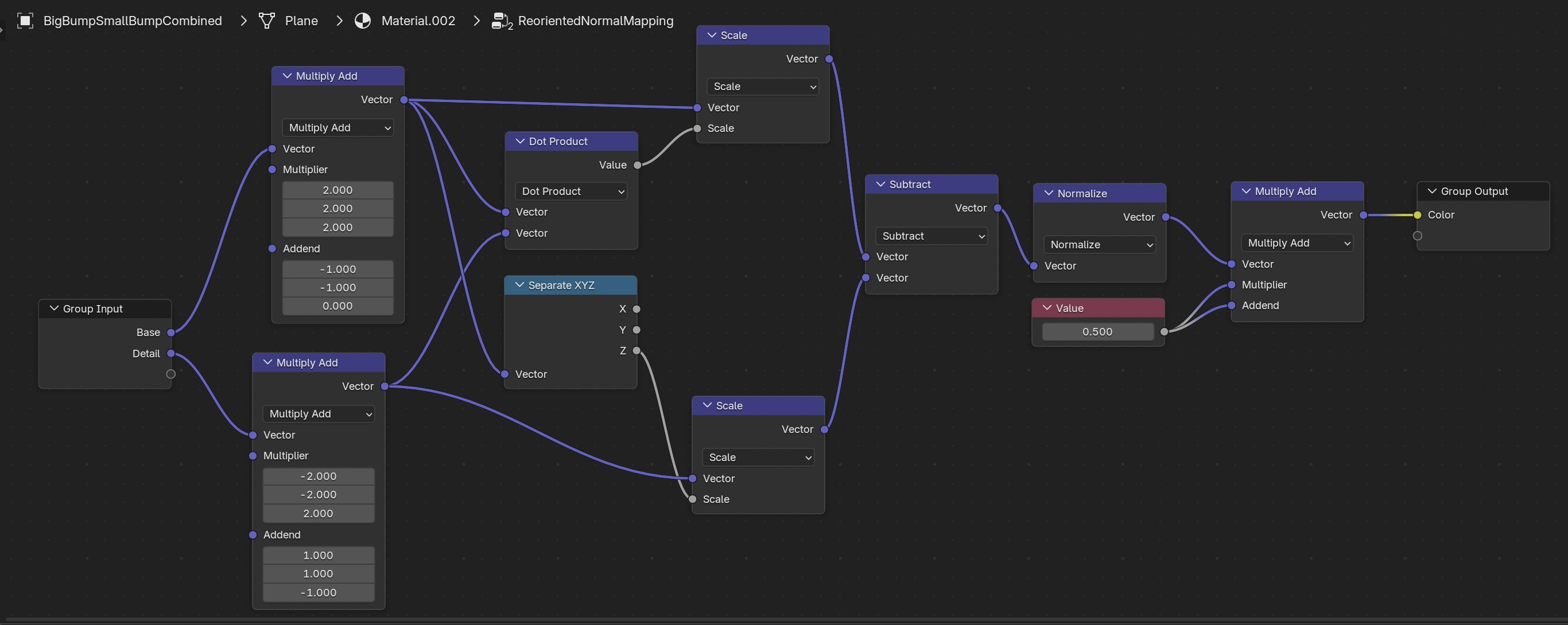
And the formulas become the Blender geometry node group for the RNM method.
Hair
Blender 3.5 has a new hair system using geometry nodes which replaces the old particle system for hair. There is an introductory tutorial on How to Create Realistic Hair in Blender 3.5 New Hair System and an in depth tutorial from Blender Studio
Wig
My figure has complicated UV islands which partially overlap. So I cannot use the hair system on it directly. I will create a separate mesh for a wig with a simple UV map, place the hair on that instead. After that the wig is locked to the skull and moves with it.
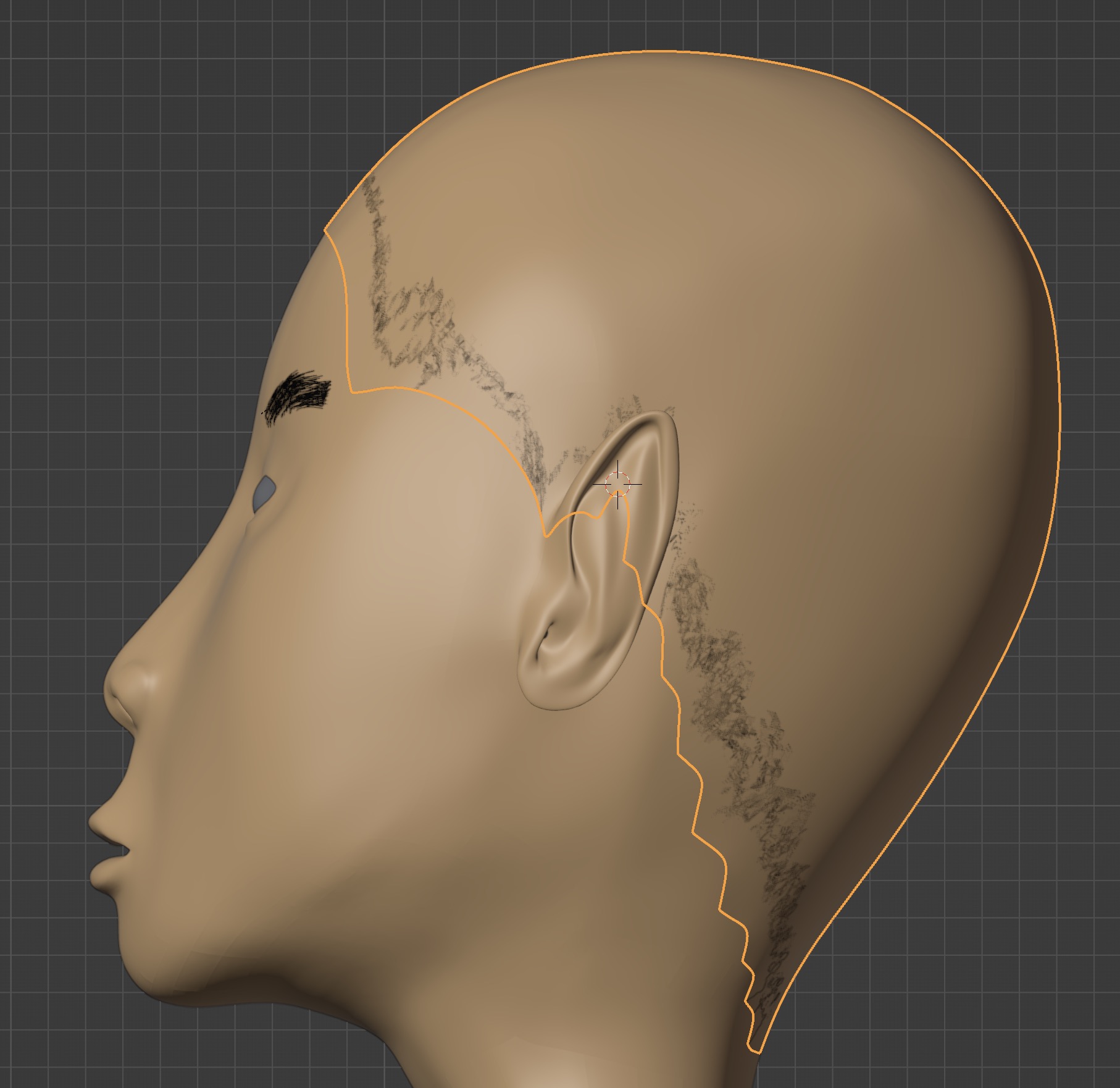
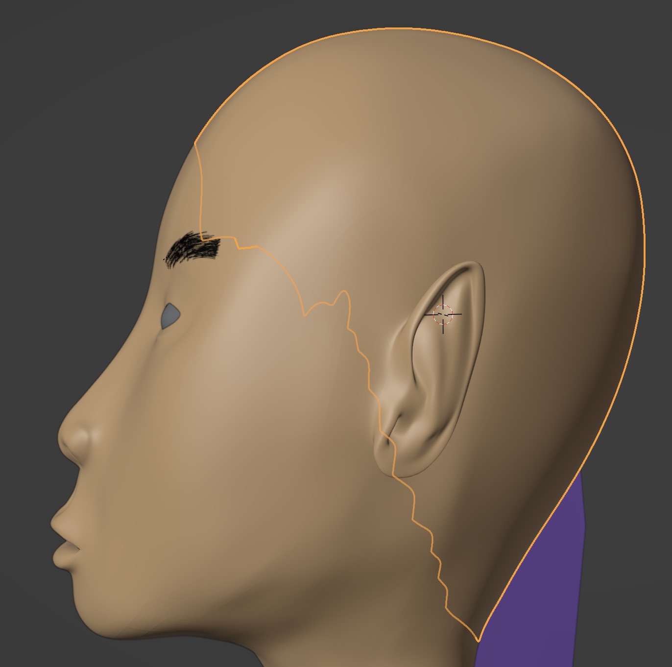
First, go into edit mode and use B (box) or C (circle)
selection modes to select the hairline in vertex, edge, or face mode.
Hold down SHIFT key to deselect and make minor adjustments to your selection.
Hit ESC to finish.
I used a reference photo of a female with a very short haircut to figure out a reasonable hairline.
Selection is faster if you toggle on X-Ray mode Option Z because you can select
both sides of the head at the same time.
Duplicate the mesh with Shift D RETURN. Detach this mesh as a separate object
from its parent head meash using P, choosing
By Selection.
You will now see the wig as a new object in the outliner; rename it to wig.
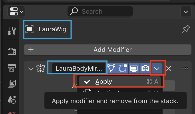
The wig inherits the mirror modifier of the female model.
In the wig's Mirror Modifier,
do Apply to generate a complete mesh.
This removes the modifier so we can place the hair on the entire wig,
The wig is the same size as the head, so you'll have a duplicate render of wig and skull. The 3D view shows overlap in some places because they aren't exactly identical. We'll fix that now.
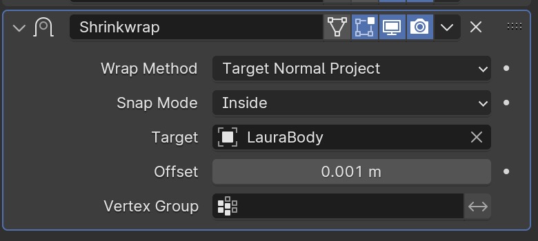
Select the wig and add the Shrinkwrap modifier.
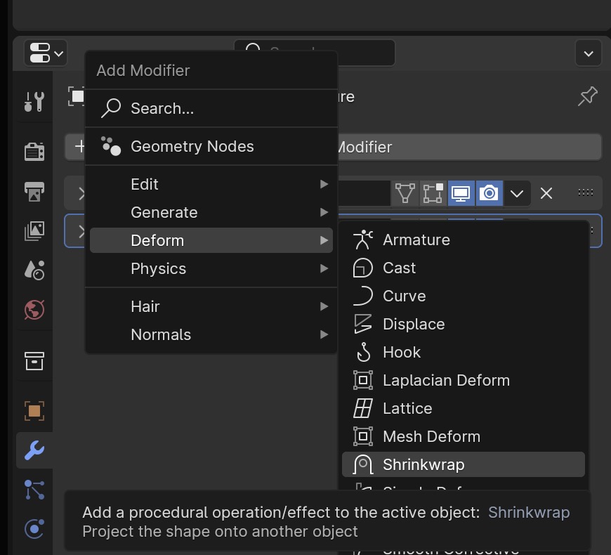
Now select body as the target for the wig to shrink wrap onto,
using Target ➤ Object ➤ Eyedropper tool
Next, let's shrink the wig slightly smaller than the head so it doesn't render on top of the skull.
We must shrink along the direction of the normals to the head surface,
Wrap Method ➤ Target Normal Project, keep the wig inside the head surface
using Snap Mode ➤ Inside, and use the smallest positive
Offset so the wig doesn't intersect the head, which I found is 2mm.
This gives us the final wig with no overlaps with the head.
Creating Hair
We will add hair to our model's head using the Blender 3.5 new hair system based on geometry nodes.
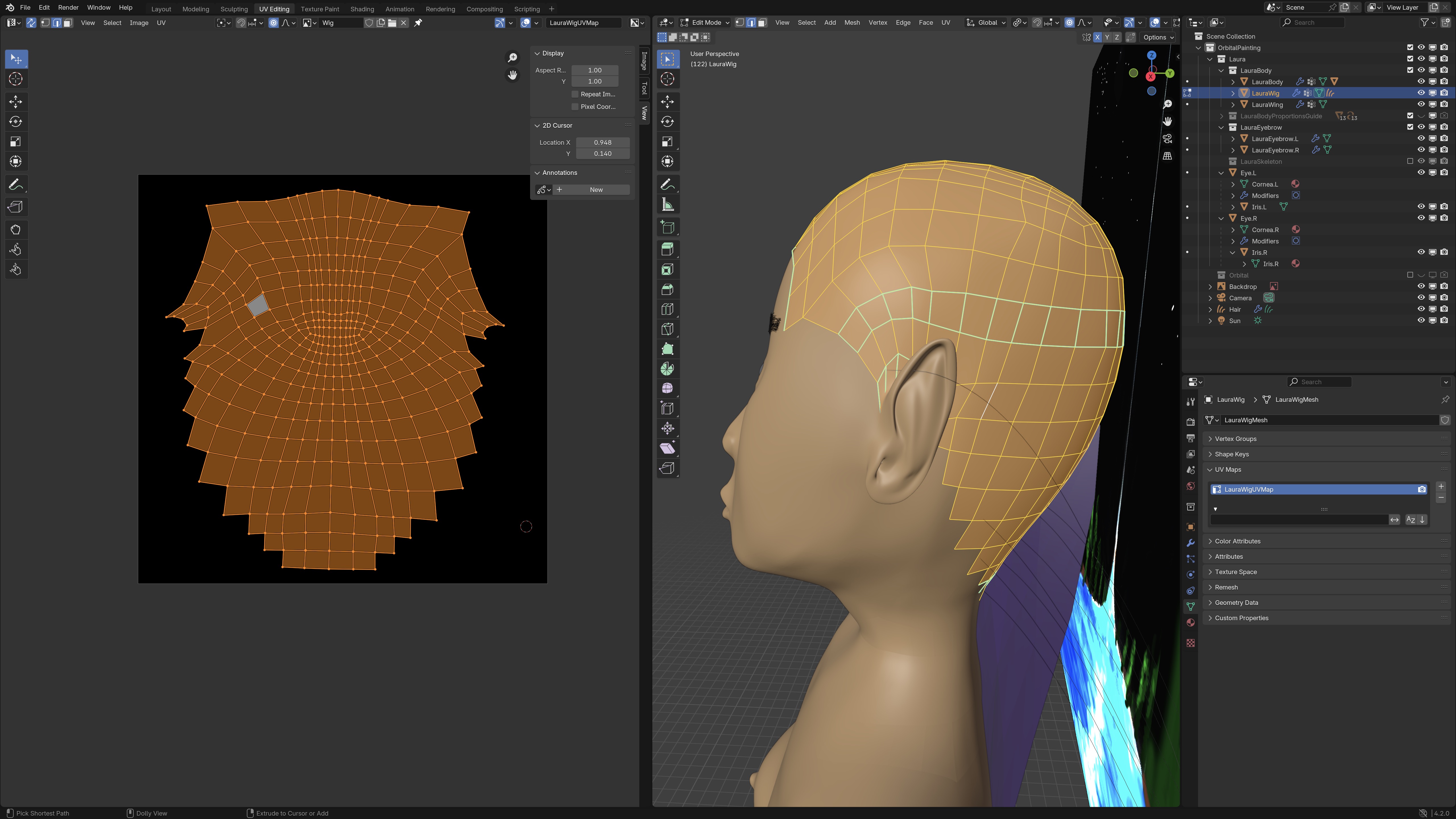
UV Map for Wig
The wig object must have a UV map with no overlapping UV islands.
Go into the UV Editing Tab
Delete any old UV maps in the UV Maps section using -
Start clean by tabbing into Edit Mode, selecting the entire mesh with A,
deleting any old meshes with U ➤ Reset
Delete any seams inherited from the parent head by selecting the entire mesh with A,
then Ctrl E ➤ Clear Seam
Now with the entire mesh selected, unwrap it with U ➤ Unwrap. In the left pane you'll see the
mesh on a gray image grid background (because you don't have an image created for the UV yet).
If you put the cursor in an island of the UV mesh in the left pane, you can select the connected vertices with
L then rotate with Ror scale with S
Hair Curves
Select the wig, then add an empty hair curve with Shift A.
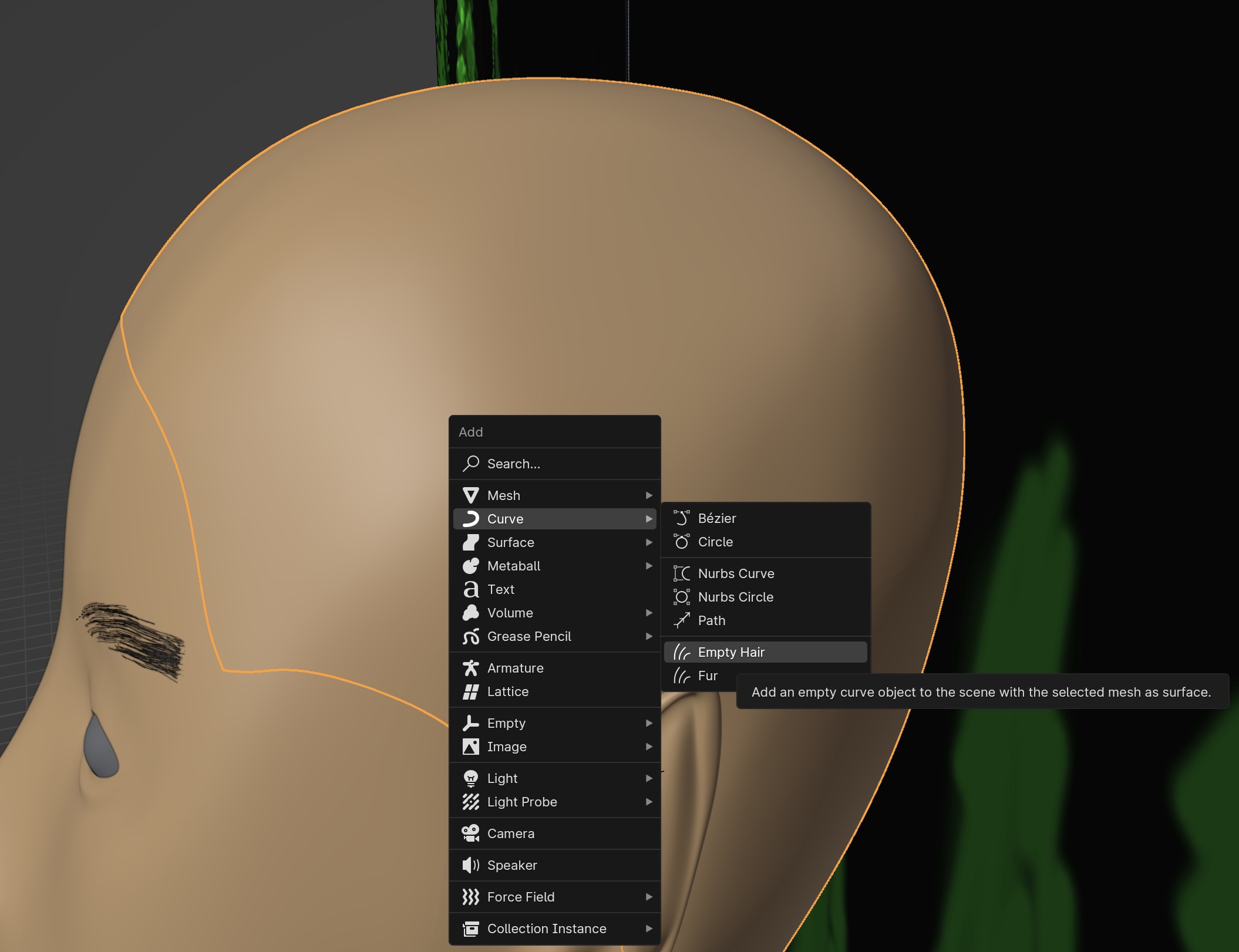
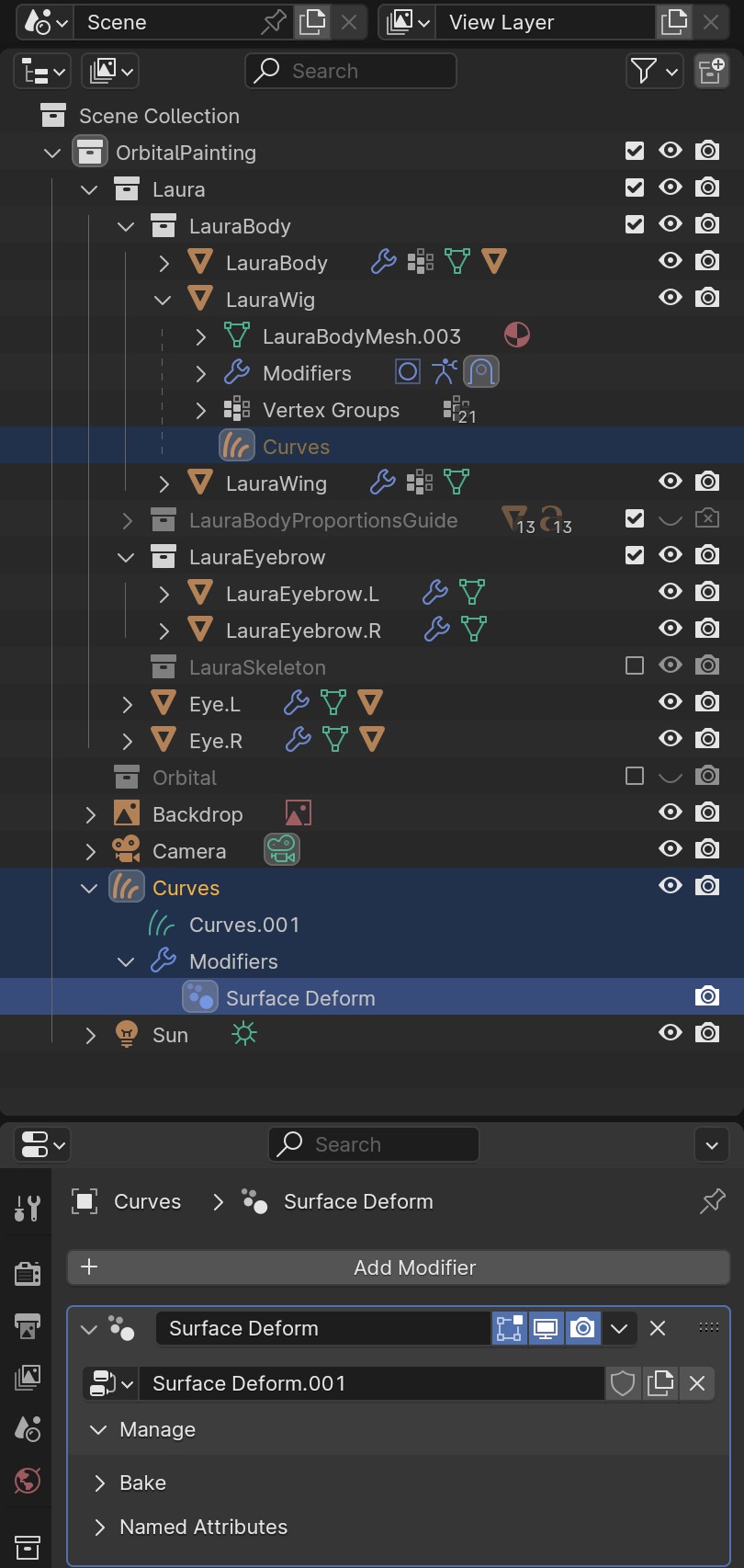
In the Outliner Panel you'll see the wig has a new Hair Curves object. You might as well rename them from Curves to Hair
There's also a Surface Deform modifier for the Curves object.
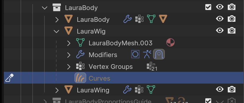
Go into Object Mode, then select the Hair Curves object under the Wig object in the
Outliner Panel.
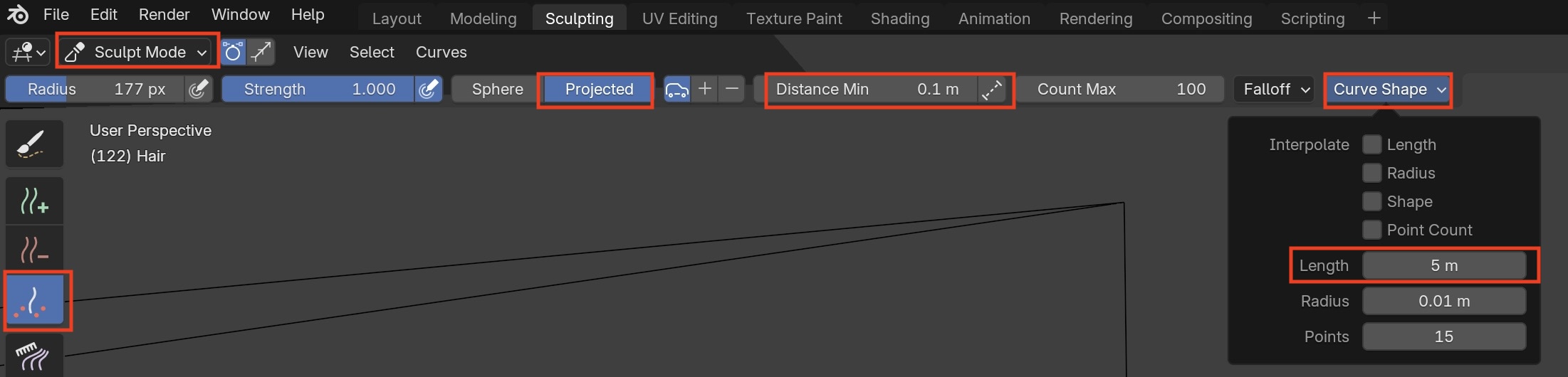
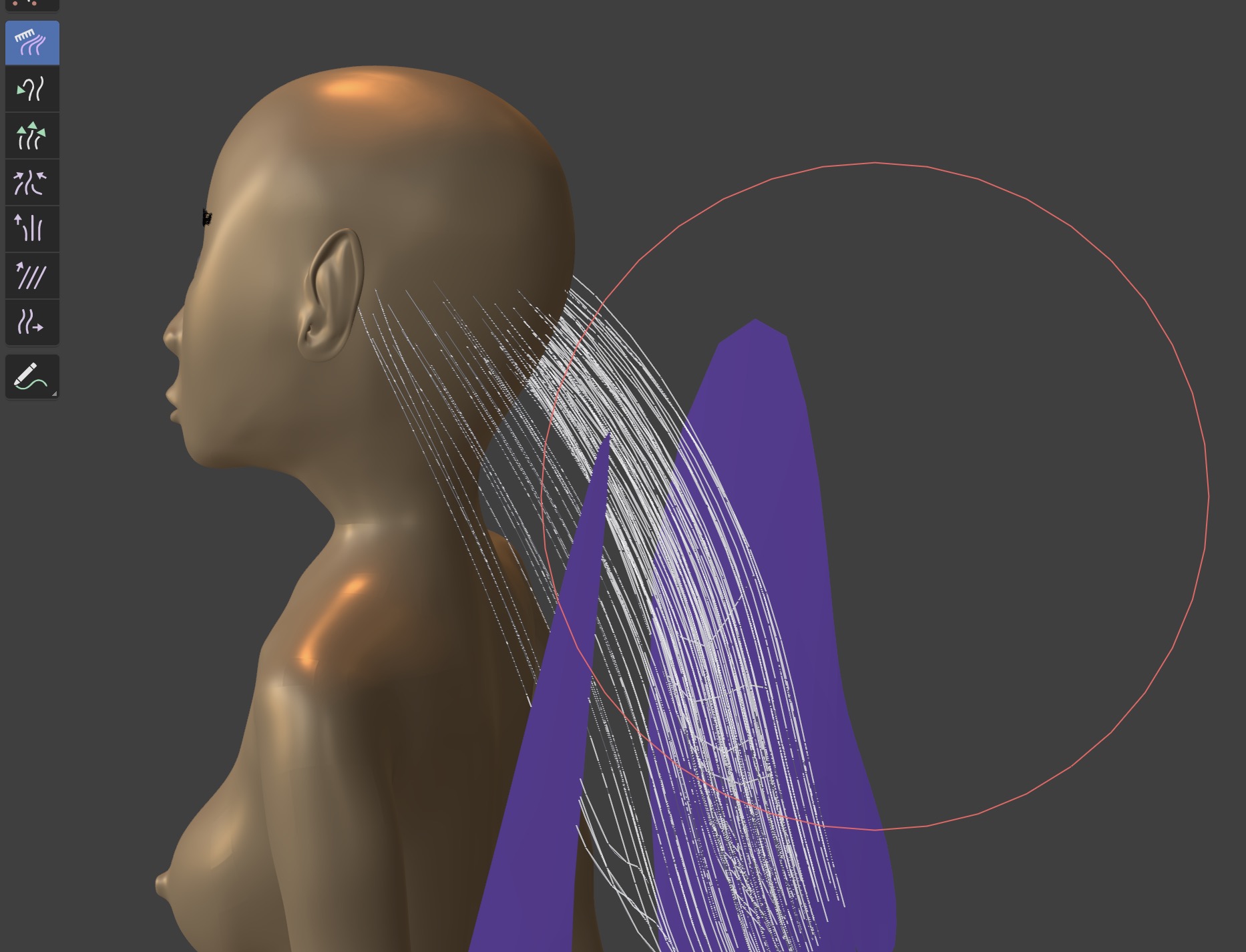
Then switch into Sculpt Mode.
You must select the curves object, or you won't see the hair sculpting controls, but rather the default sculpting controls
Select the density brush,
set Distance Minimum (the distance between hair roots) to 0.1m, set
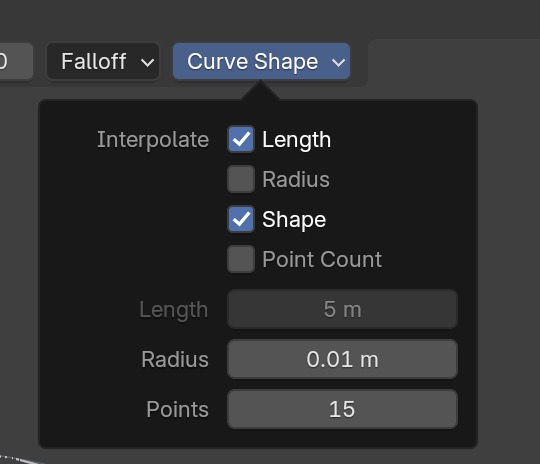
Curve Shape ➤ Length to 5m
and number of control
Points to 15 to get maximium smoothness in the curves, and
falloff to Projected.
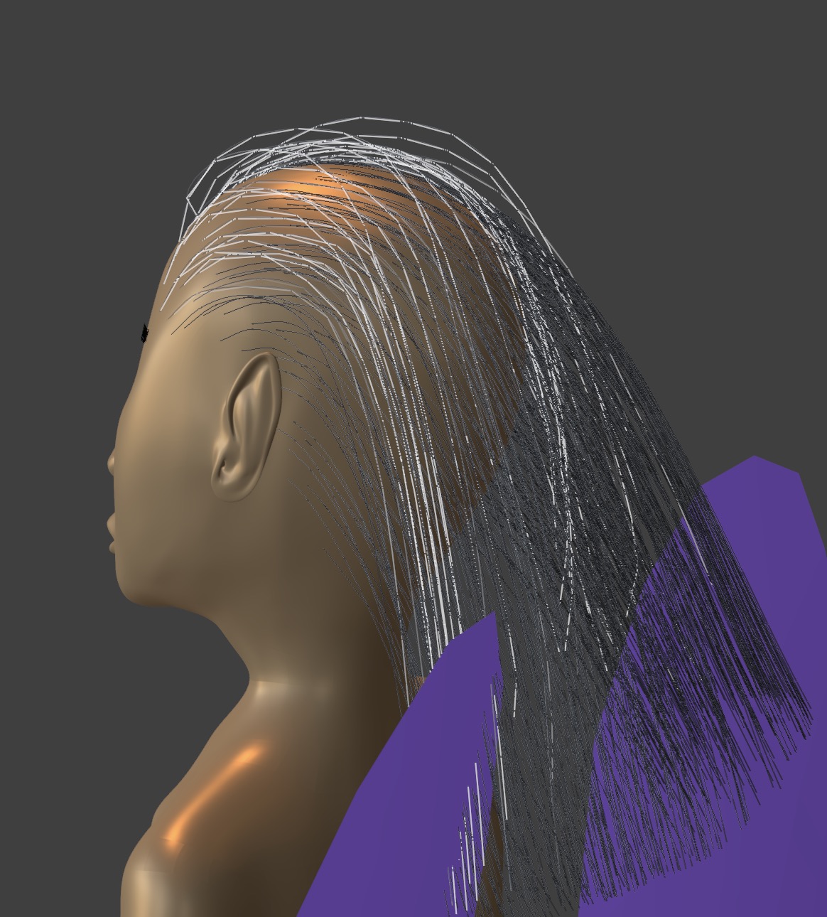
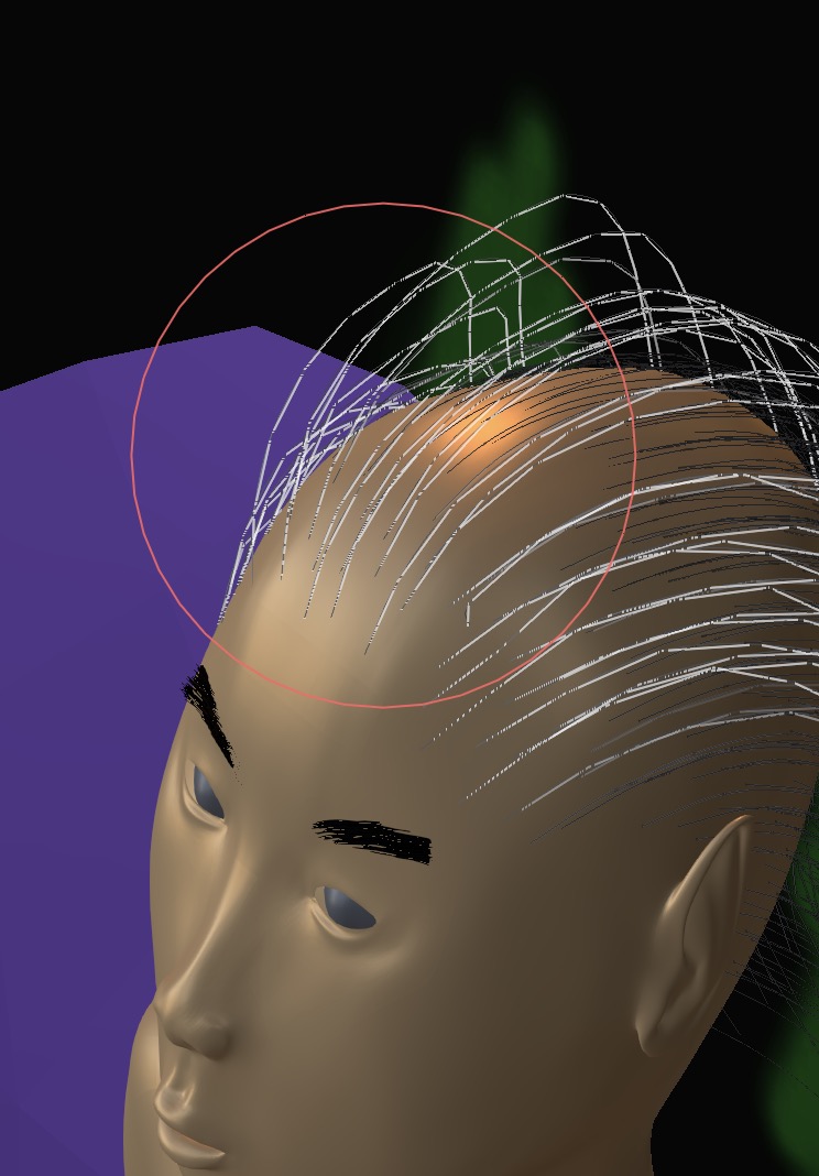
You can now paint with the density brush on the model. Use the F key to change the brush size.
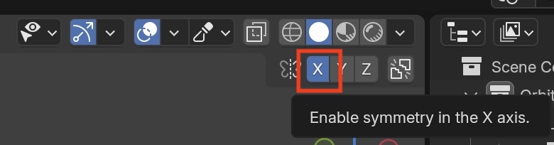
I assume you have generated your model symmetric to the x-axis, so you can turn on x-symmetry when you add hair.
 A quick brush across the wig shows really thick hairs!
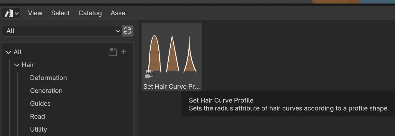
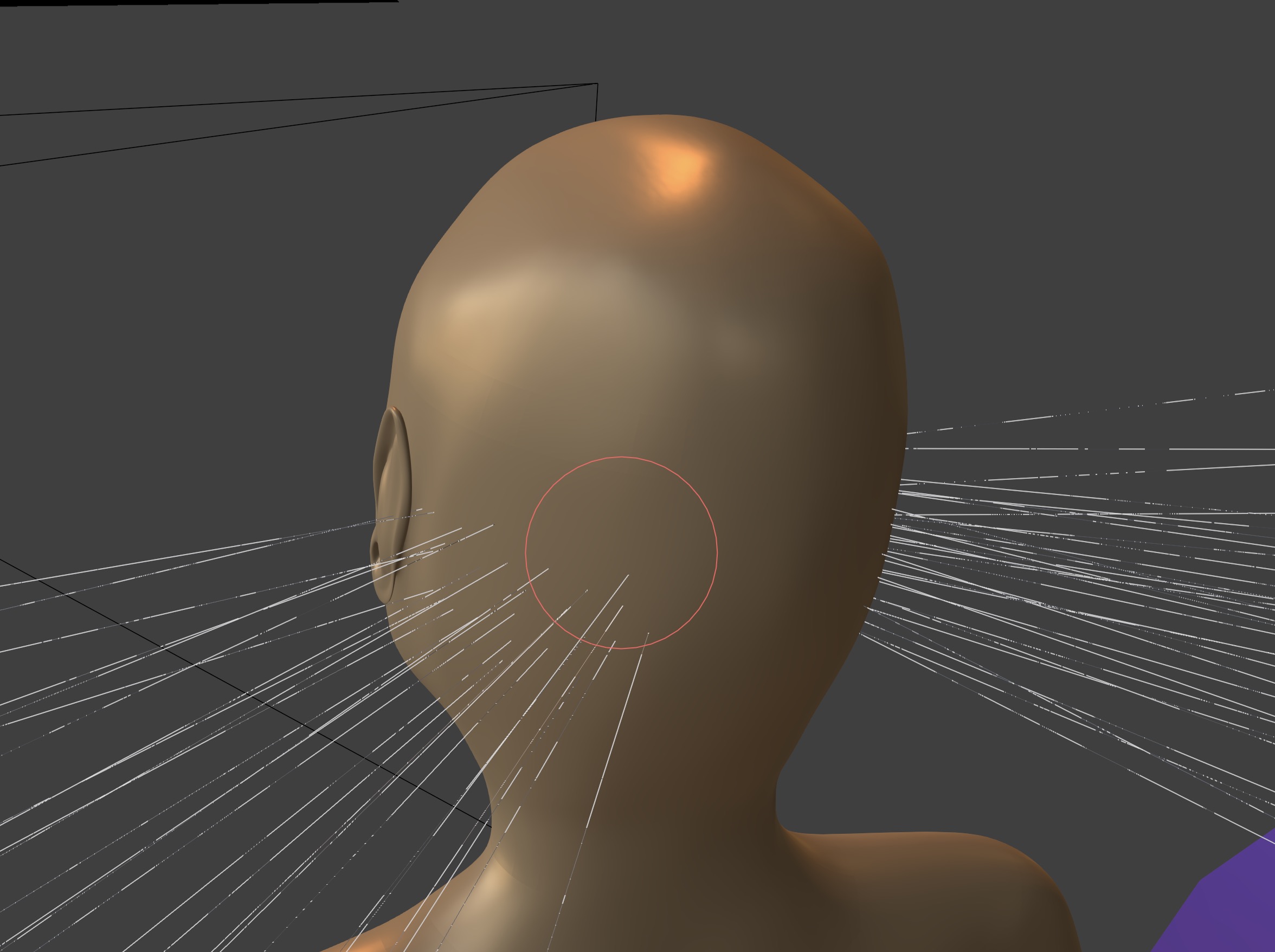 This is the default hair profile which we have to change.
From the Asset Browser select the Hair Curve Proile
asset in Write and drag and drop onto the selected hair.
Adjust the hair thickness. I set the hair root to 0.5mm
This is the default hair profile which we have to change.
From the Asset Browser select the Hair Curve Proile
asset in Write and drag and drop onto the selected hair.
Adjust the hair thickness. I set the hair root to 0.5mm
Before you comb the hair, enable the sculpt collision option.
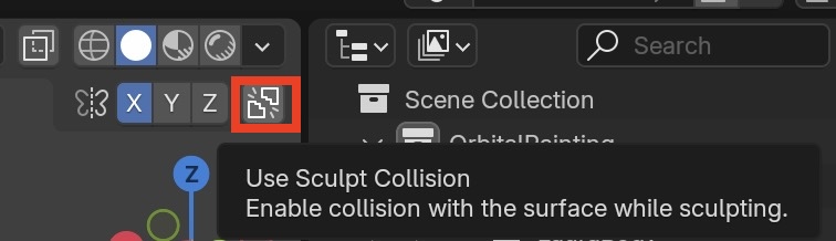 This prevents the hair from going through the wig (but the hair can still penetrate other objects
such as the body).
Then comb the hair with the Comb Brush
This prevents the hair from going through the wig (but the hair can still penetrate other objects
such as the body).
Then comb the hair with the Comb Brush
Select the Density brush again,
enable Curve Shape ➤ toggle Length, Shape
 This will add new hair based on the existing hair curves orientation and shape.
You can select any hair curves using the Paint Selection brush, then switch to the Puff brush so the forehead hairs don't lie so flat. Selected hairs are white and all other hairs are black.
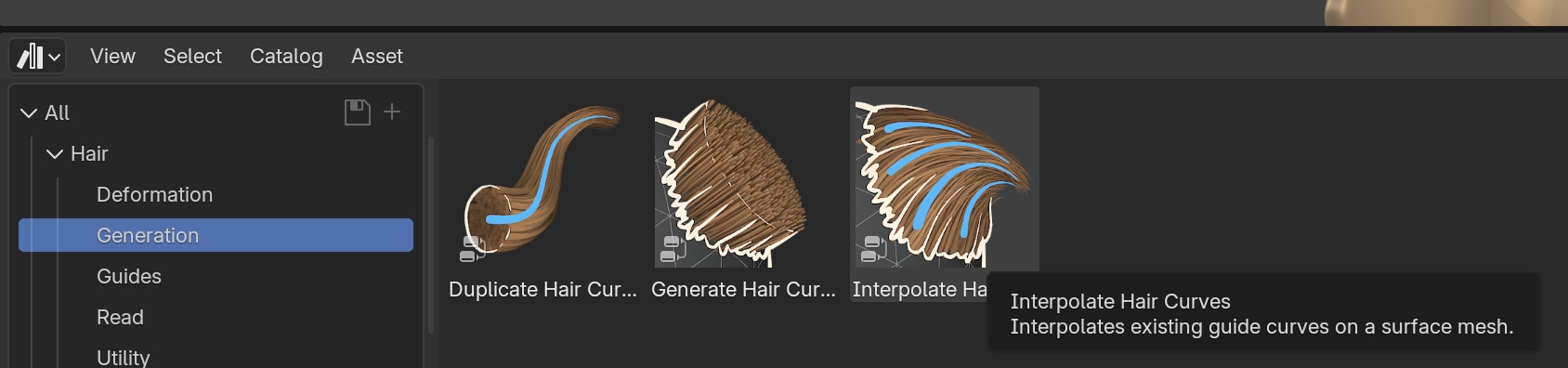
The hair curves we have sparsely placed are called guide curves. Next we generate many more hairs using interpolation. From the Asset Browser select the Interpolate Hair Curves
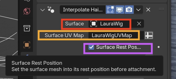
From the Asset Browser select the Interpolate Hair Curves asset in Generation and drag and drop onto the selected hair.
Notice the difference when we toggle interpolate hair on and off in the viewport display:
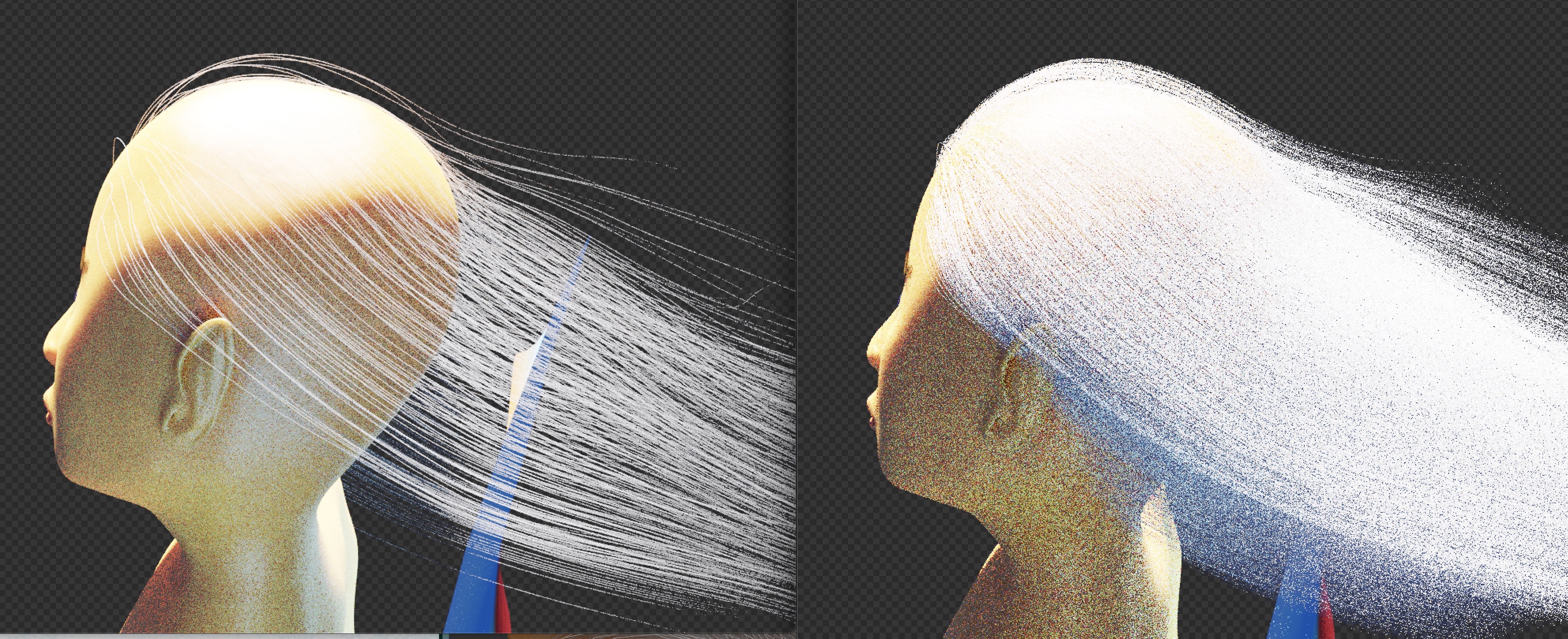
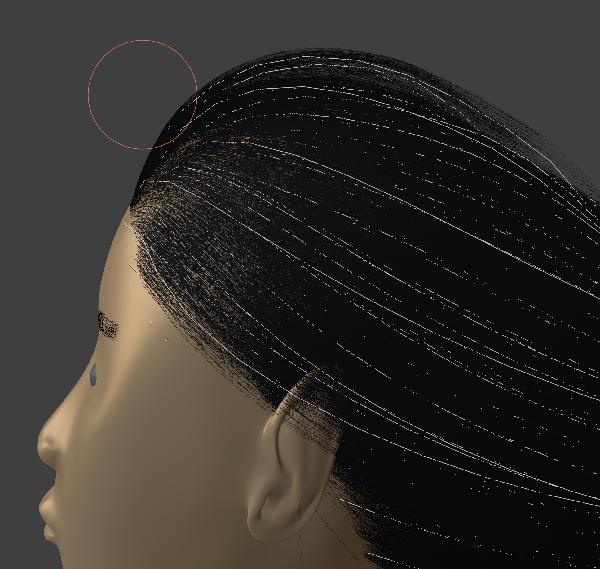
The hair is default white so change it to black in the viewport.
Notice if you are in sculpt mode, when you select the hair, only the guide curves are selected (white)
and not the interpolated curves (black). That's a nice convenience.
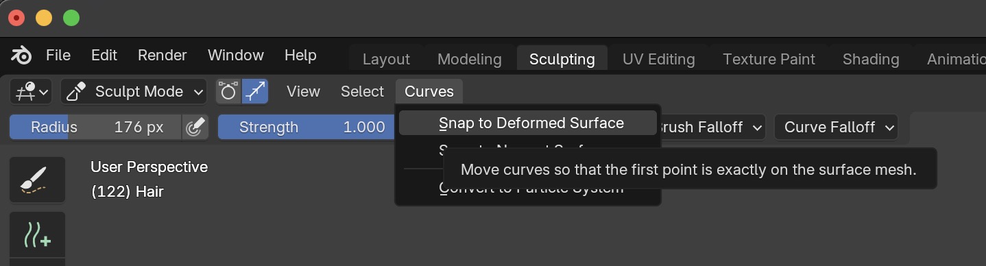
If the wig size changes, the hair curves won't automatically by synchronized to the change.
In Sculpt Mode you will have to do this manually by Select Hairs ➤ Curves ➤ Snap to Deformed Surface
Hair Color and Texture
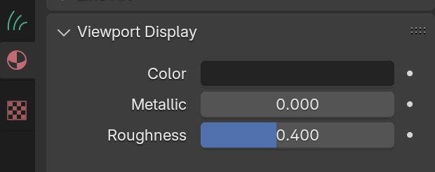
The wig mesh has skin as its default material. As it stands, the hair material, since it's emitted from the wig mesh, will inherit the skin color, which is wrong. So we need to add a new material for hair. Use the principled hair shader. Since my figure has black hair, I'm using the melanin parameters rather than direct colors.
I was getting bright white shiny highlights on the hair. Lowering the sun brightness and increasing the environmental lighting helped somewhat, but there was still too much, so I changed the default offset to a large negative number to push the glint away from most of the hair.
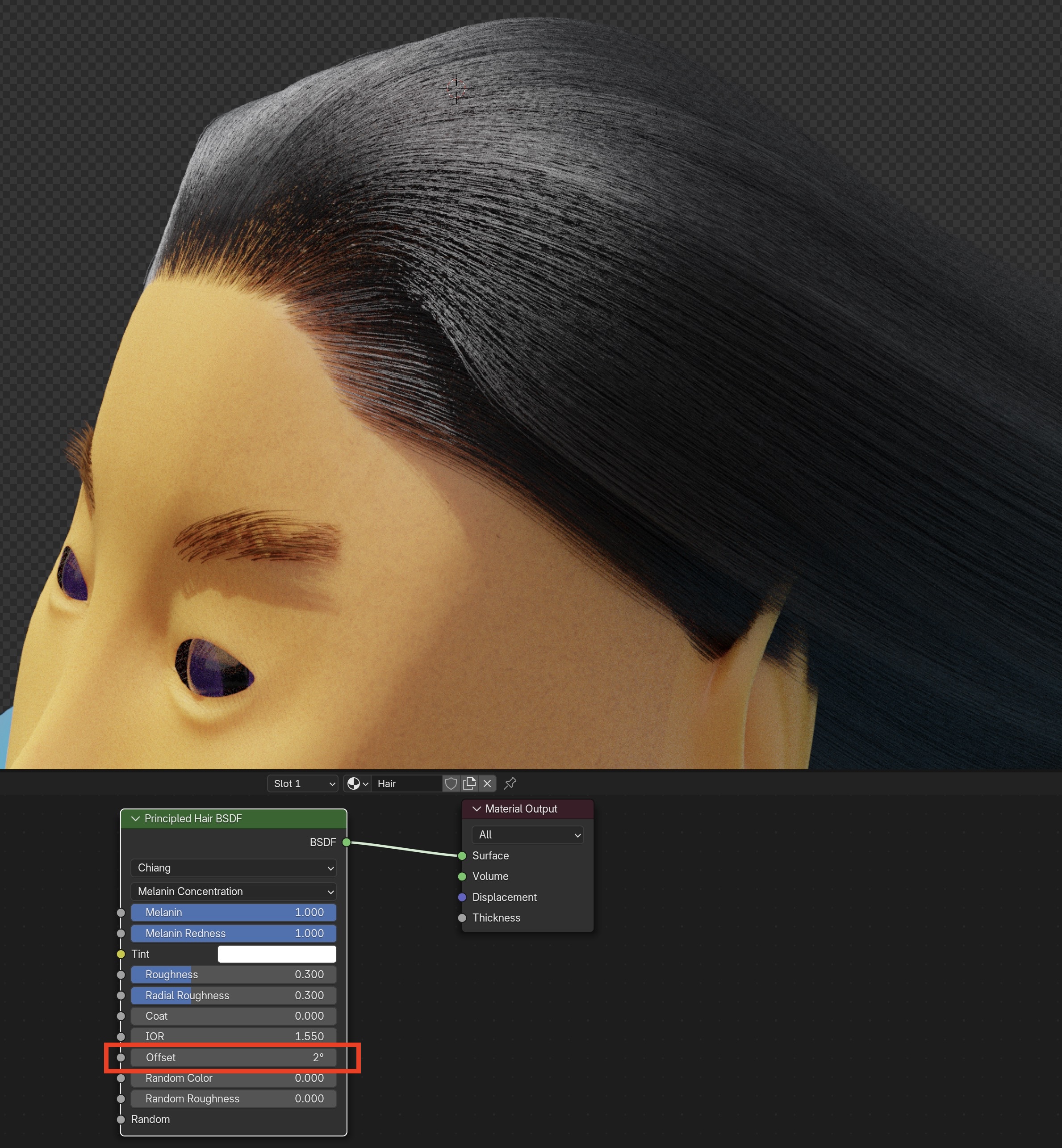
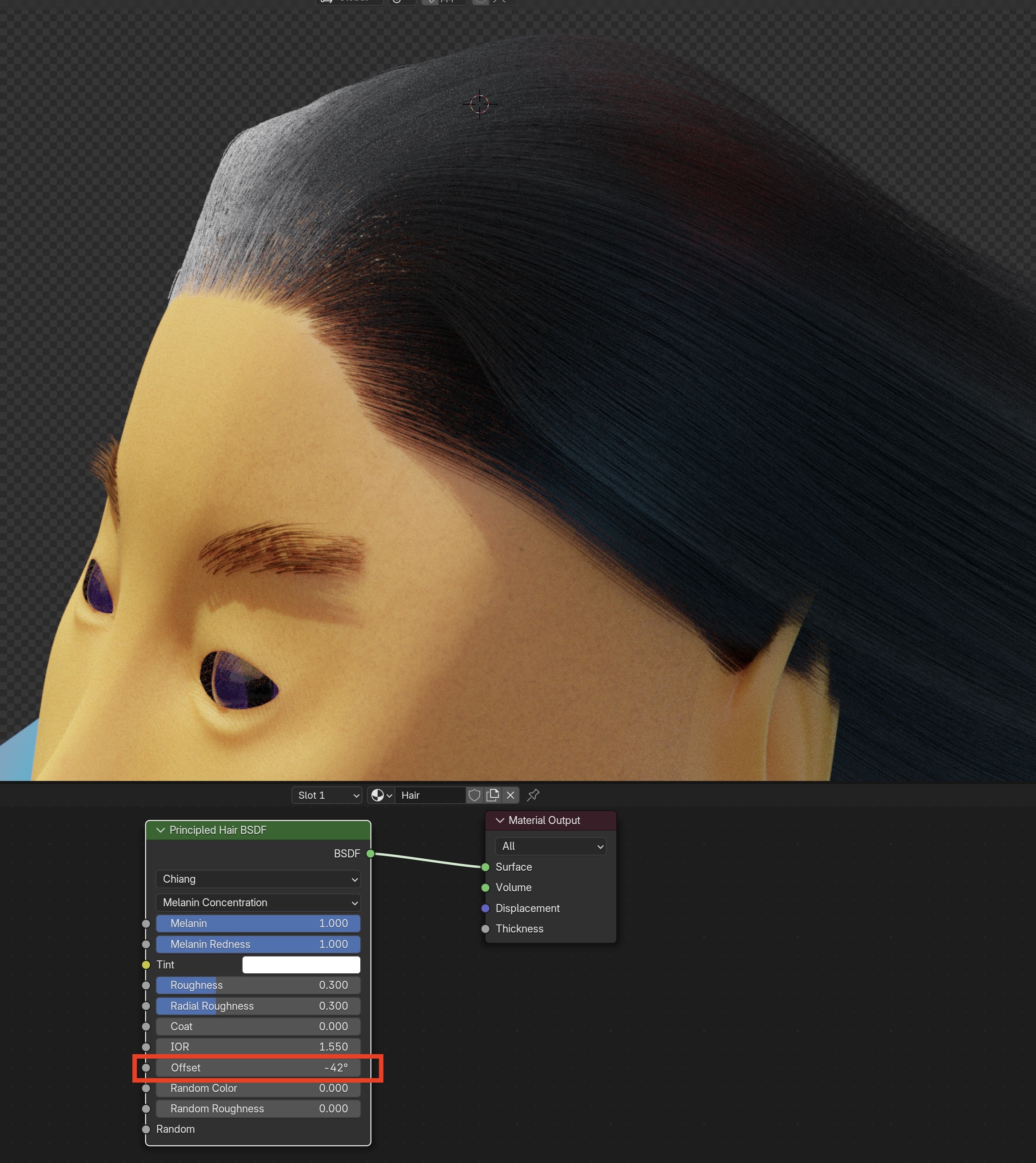
Eyebrows
To create eyebrows, create two objects eyebrow.L and eyebrow.R consisting of planar mesh.
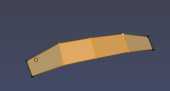
Parent each eyebrow to the head bone by selecting it, then shift selecting the head bone as parent object and using Ctrl-P Set Parent to Bone. Now the wig and both eyebrows have the head bone as parent.
Add hair as above, adding a particle system, materials, combing and so on.
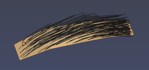
Position the eyebrows and move the vertices just below the skin surface so we render the hair only.
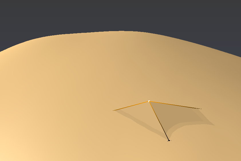
Toggle the wireframe mode with z to see the vertices below the skin more easily.
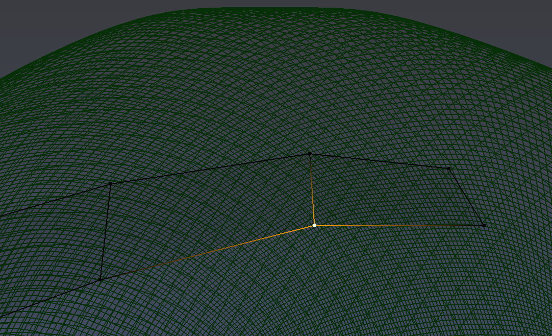
I cloned the material for the hair in the eyebrows, but modified to make it use finer hairs and different colors.
The color of the object, I left as the default skin material.
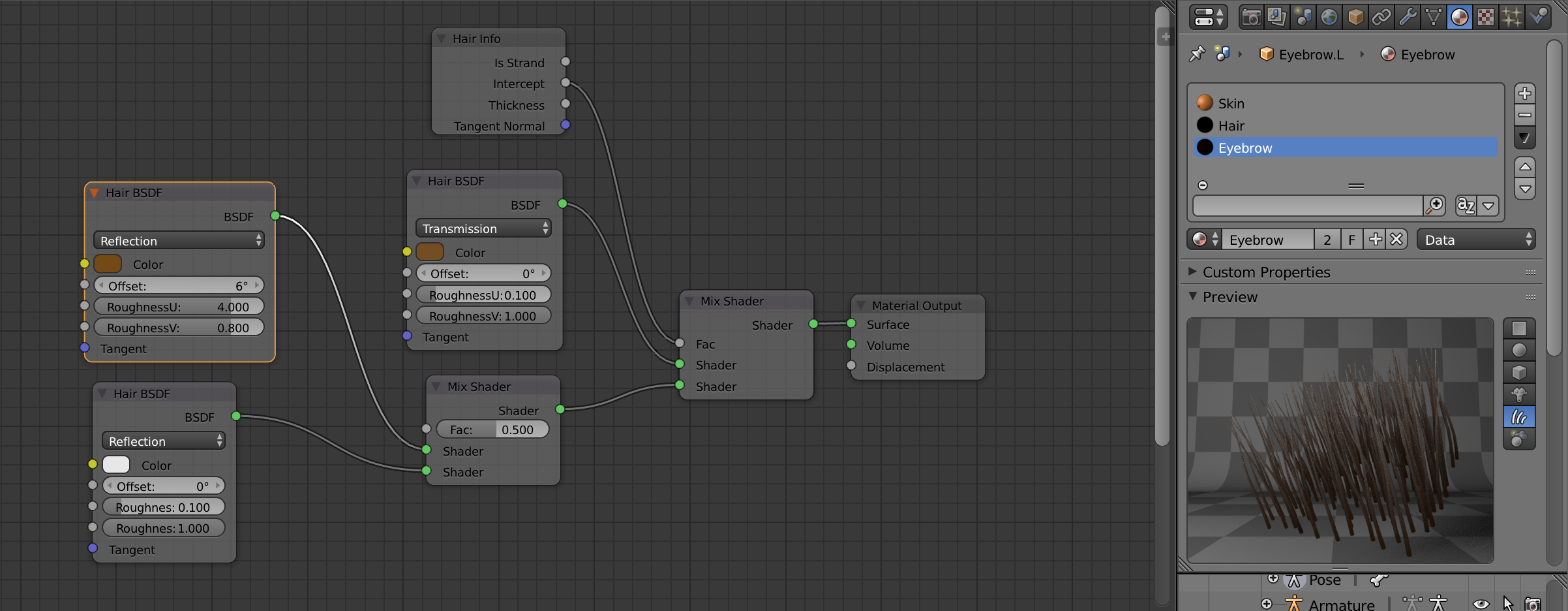 Assign the new eyebrow material in the hair particle system for the eyebrows,
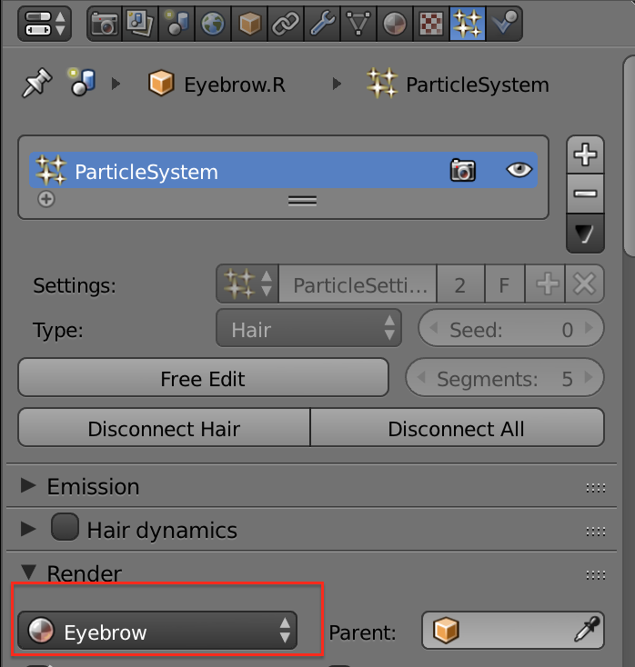
Finally do a test render in the viewport:
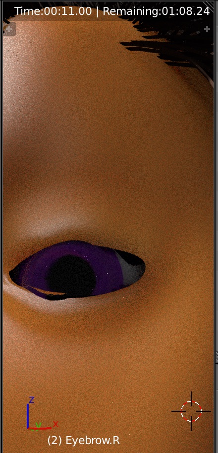
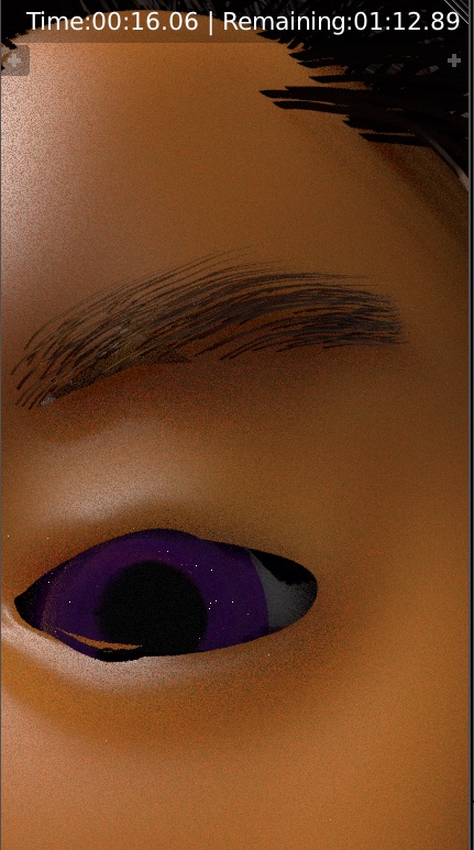
Eyes
I followed most of this tutorial on CG Cookie - Creating a Procedural Eyeball except that I use UV mapped image textures instead of procedures.
Creating the Eyeball and Iris Meshes
Place the 3D cursor at a convenient spot.
Create the eyeball by adding a UV Sphere using Shift A ➤ Mesh ➤ UV Sphere
Dial down the radius to 1.25cm and keep the other defaults.
Now we will smooth out the mesh geometry to avoid shading artifacts.
Select the vertex the pole, and delete the fan geometry, then select the edge loop with Shift Double Click
on one of the loop edges.
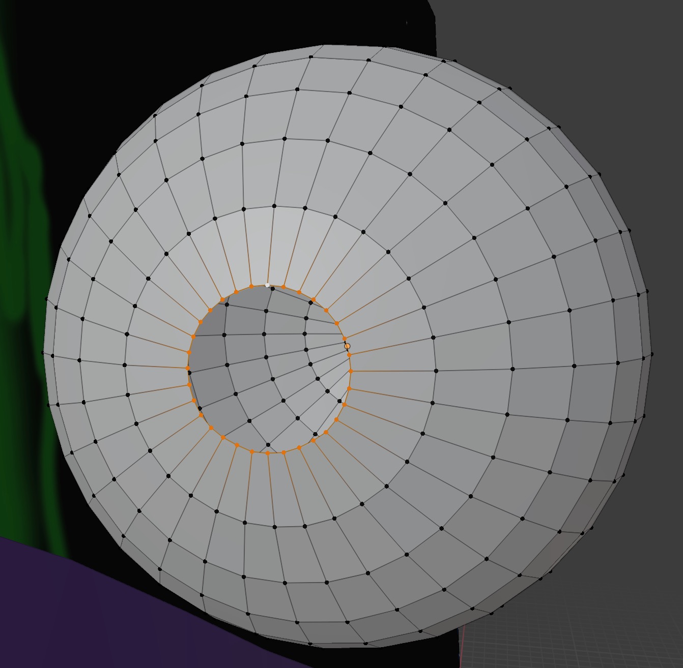 Fill with a quad grid using Shift Spacebar ➤ Grid Fill and adjust the span and offset
to get a smooth even grid.
Fill with a quad grid using Shift Spacebar ➤ Grid Fill and adjust the span and offset
to get a smooth even grid.
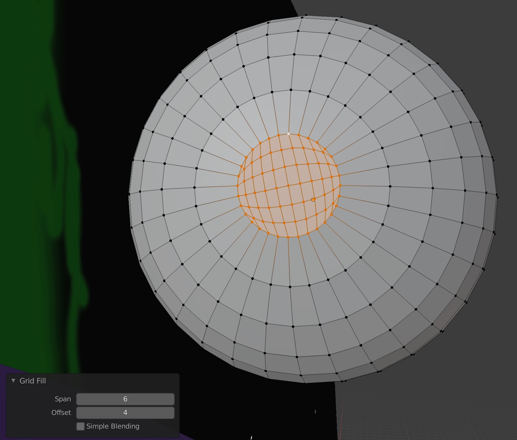
Select proportional editing with O, select a vertex in the
middle of the grid and then pull out normal to the mesh using
Alt S and dialing the strength of the influence with the
mouse scroll wheel to create the cornea shape.
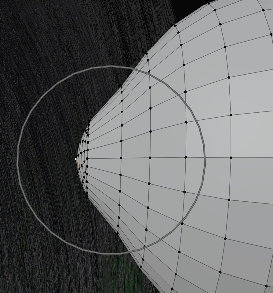 Do the same for the other pole. Add Subsurface modifier
to smooth out the mesh. I used 3 levels.
Do the same for the other pole. Add Subsurface modifier
to smooth out the mesh. I used 3 levels.
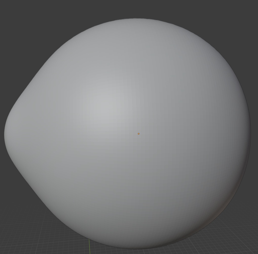
Now we do the iris. Create another UV Sphere using
Loop Select an edge at the equator.
Then select the hemisphere with
Shift ➤ Select ➤ Select Loops ➤
Select Loop Inner-Region
and delete it with X ➤ Delete Vertices.
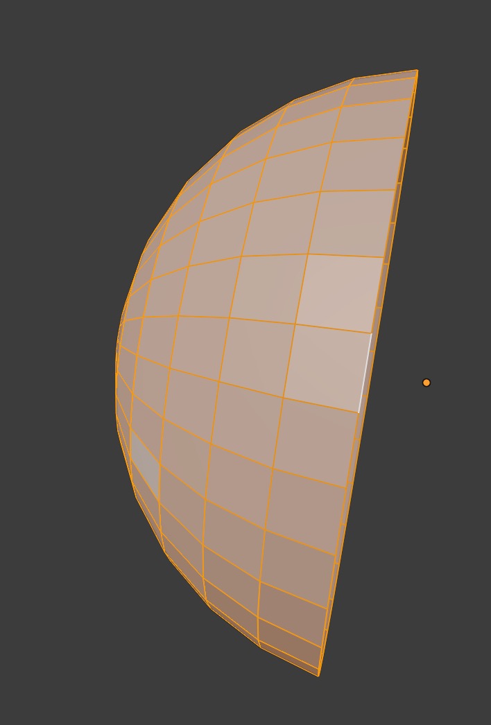 Then S Z 0 to flatten the disk.
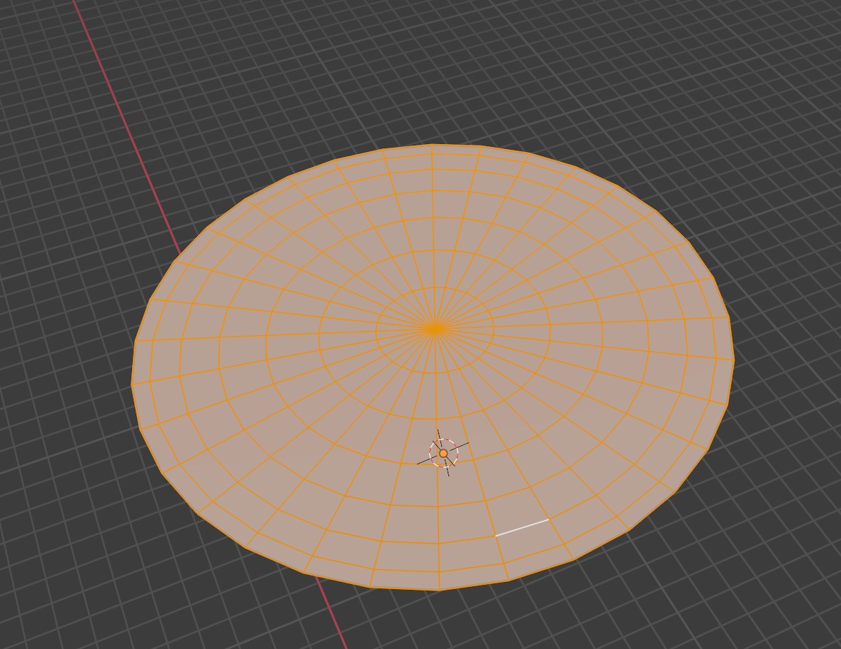 To make a pupil, select the innermost ring with Double Click on a ring edge,
Spacebar ➤ Select ➤ Select Loops ➤ Select Loop Inner-Region,
pull back the vertices, finally select the fan geometry with Shift B mouse drag
and delete the edges to leave a hole for the pupil.
To make a pupil, select the innermost ring with Double Click on a ring edge,
Spacebar ➤ Select ➤ Select Loops ➤ Select Loop Inner-Region,
pull back the vertices, finally select the fan geometry with Shift B mouse drag
and delete the edges to leave a hole for the pupil.
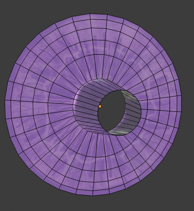
UV Uwrapping for Eyes
Go to the UV Editing Workspace.
First we create the outer surface of the eyeball, the Sclera.
Create a new image in the left panel called Sclera and use defaults.
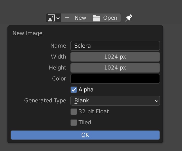 Save the image with Alt S into your /Textures
directory as an image Sclera.png
Save the image with Alt S into your /Textures
directory as an image Sclera.png
In the right panel create a new UVMap called UVMapSclera
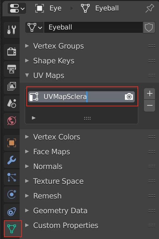
Reset any previous UV mappings U R.
Now we will select the back of the eye mesh and UV unwrap it.
Do that by toggling on x-ray mode with Alt z
and selecting
the mesh with B Mouse Drag
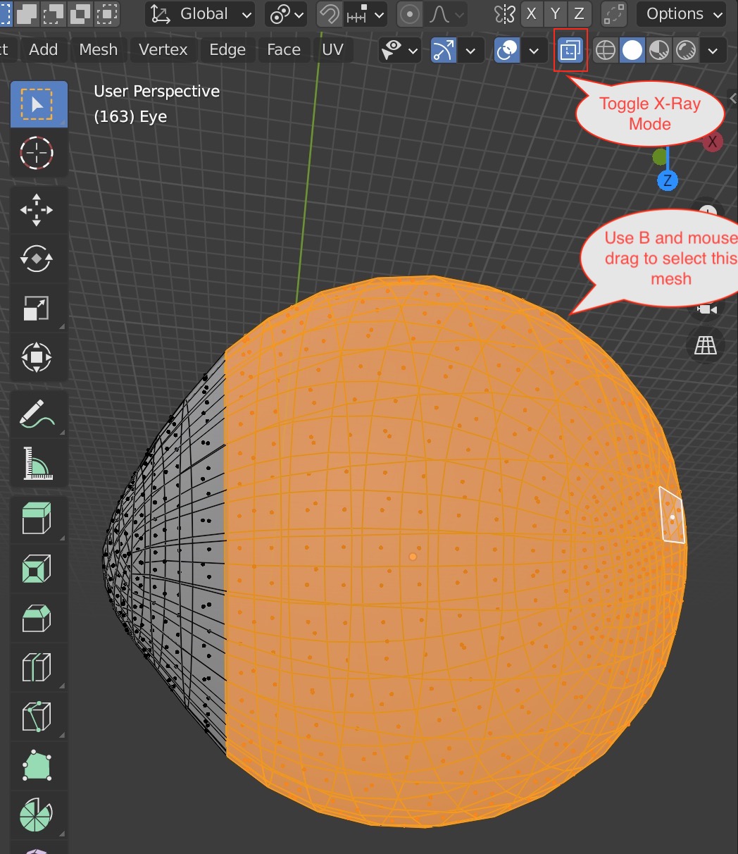 Unwrap the mesh using U. Move and shrink the island
of vertices using S and G as
one would expect.
Unwrap the mesh using U. Move and shrink the island
of vertices using S and G as
one would expect.
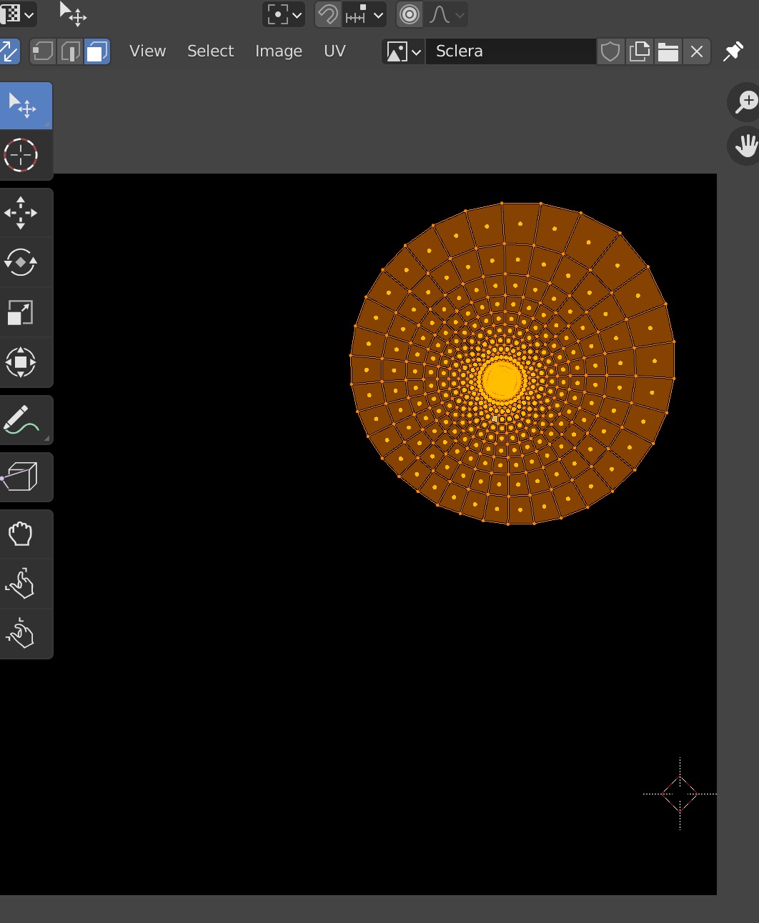 Now do the same for the cornea
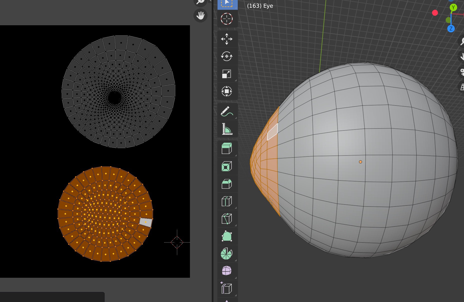 and the piece of mesh between the two.
This way we'll have three disconnected UV mesh islands
and the piece of mesh between the two.
This way we'll have three disconnected UV mesh islands
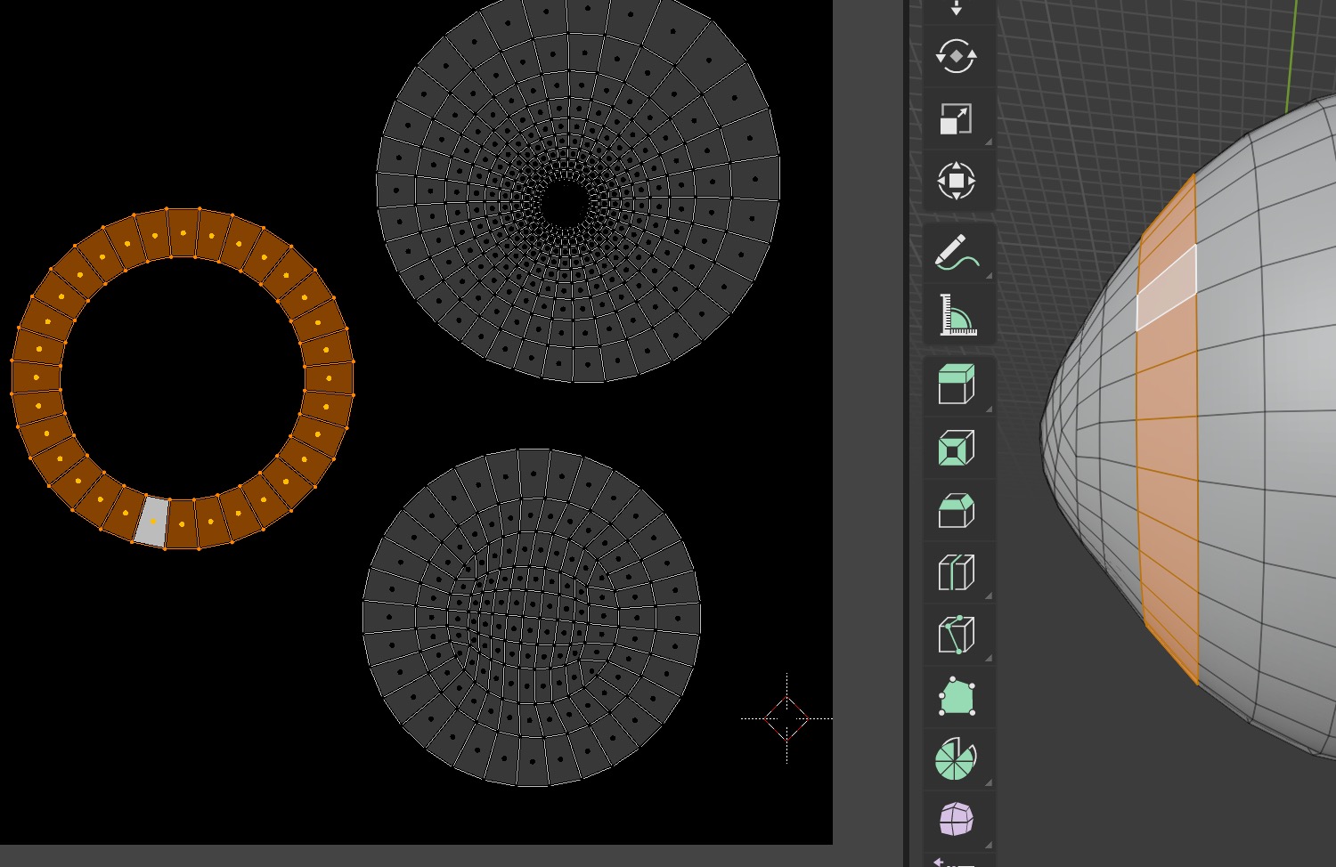
Now we need another UV Map for the cornea transparency mask.
Hit the + key to generate a new UV Map and rename it
Cornea. In the same way as above, create a new image for it, name it
Cornea.png and save it to /Textures.
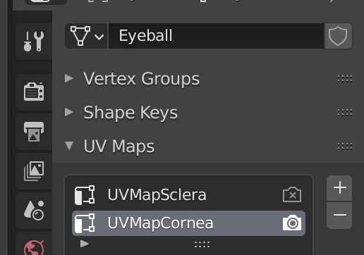
Similarly, set up a UV map for the iris.
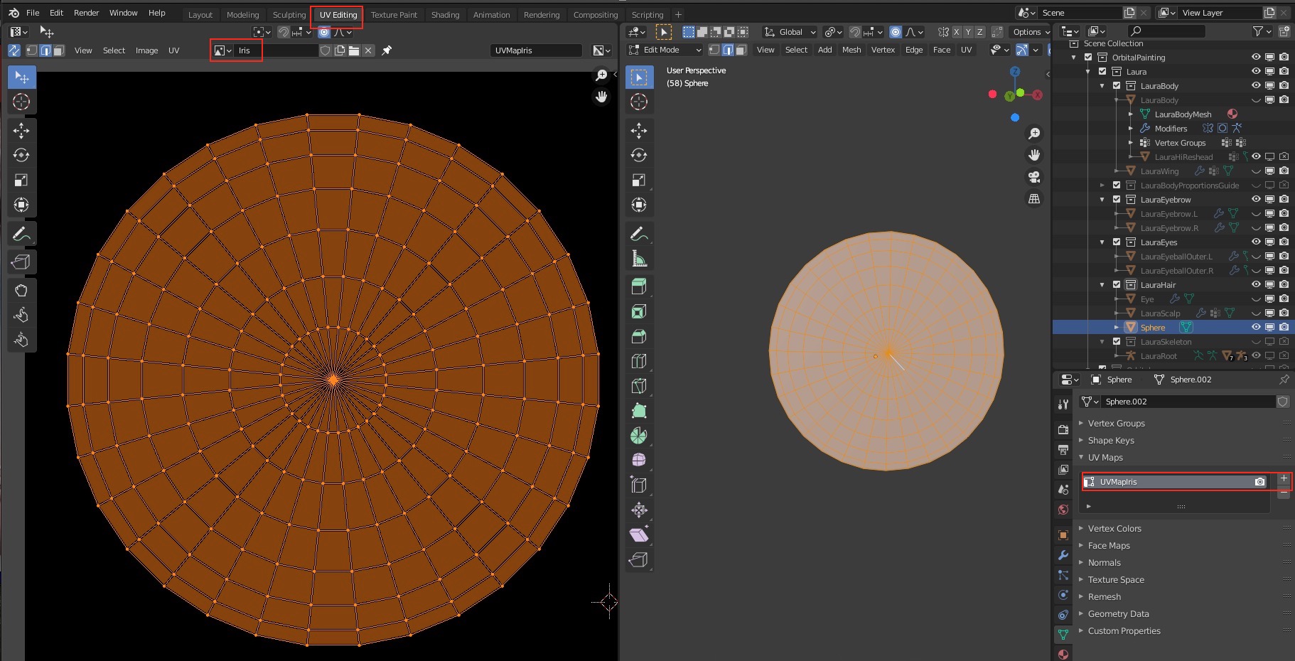
Materials for the Eyes
Let's create the materials first and color them later. We'll use the general purpose principled shader for cornea and iris.
The Sclera will be the eyeball color but the Cornea will be a Transparency Mask modulating the shader node
where white is opaque and black is transparent.
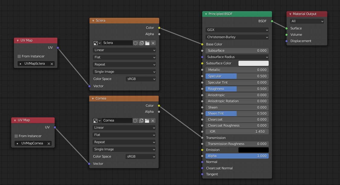
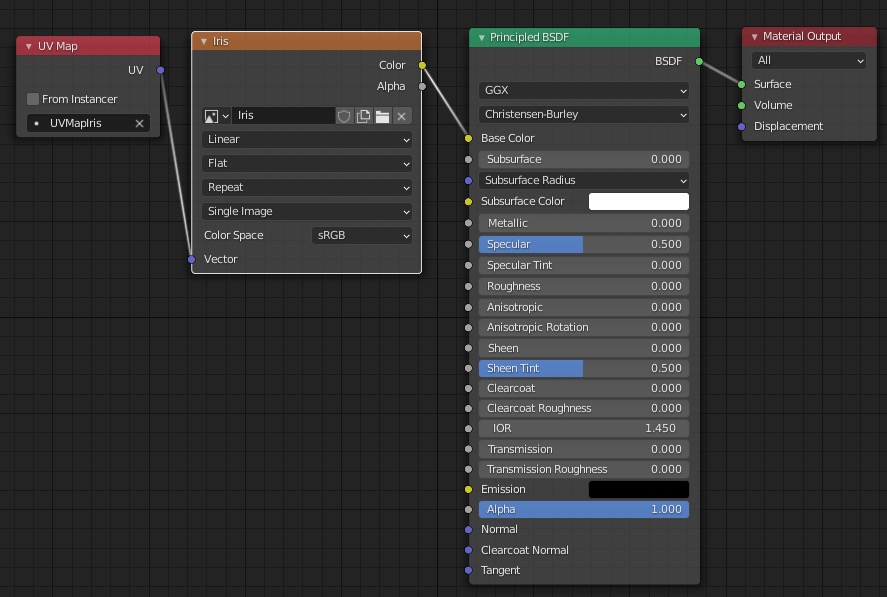
Texture Painting the Eyes
Painting the Iris
Go to the Texture Paint Tab. We'll paint the iris first.
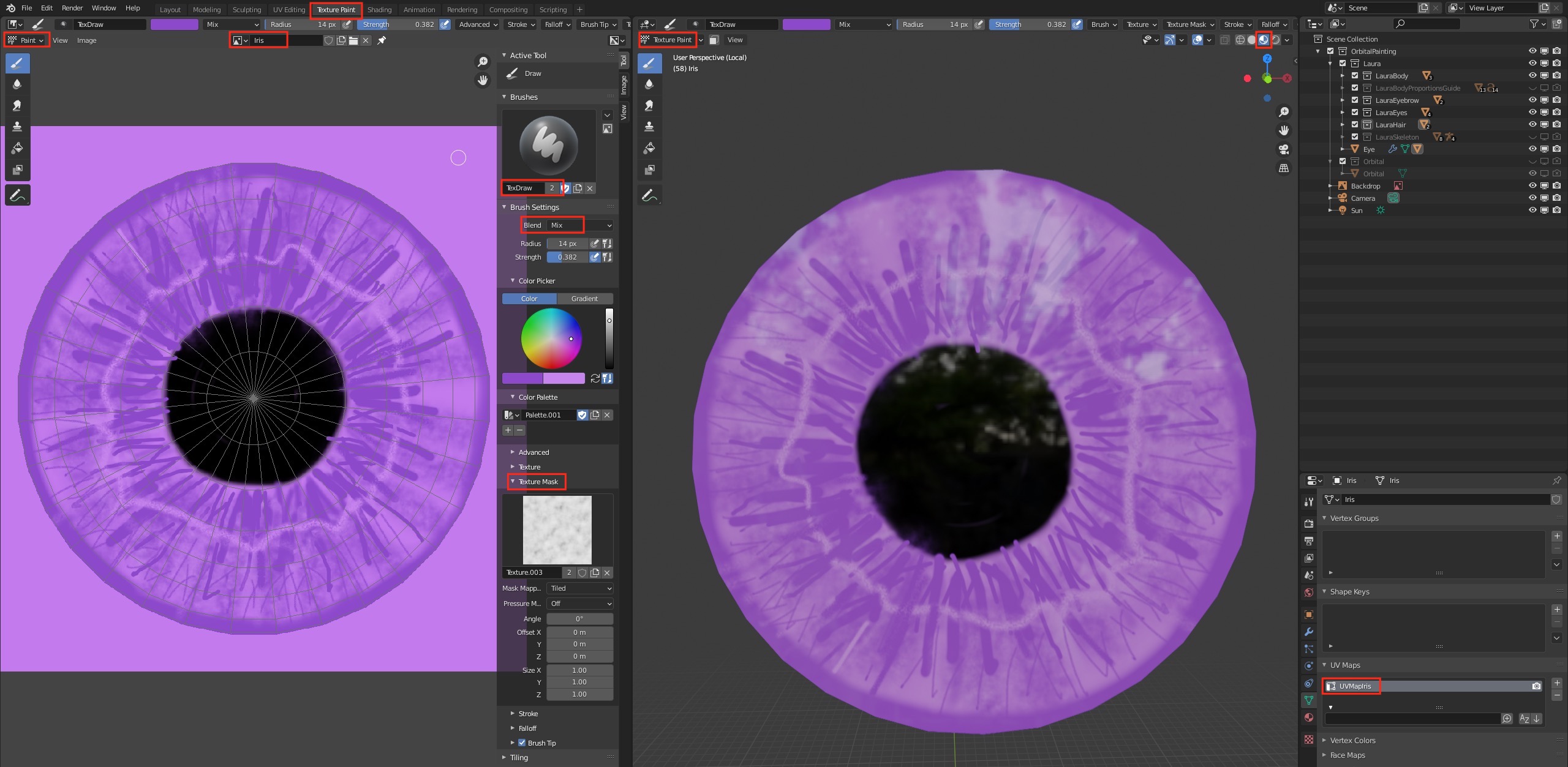
If you cannot texture paint onto the iris, check the following:
- In the Shading tab, make sure you have selected the Iris UV map node.
- Back in the texture paint panel, make sure you've selected the Iris UV Map in the Object Data Properties Panel
- Finally, check that you've actually selected the iris object as the active object.
Also check that the faces are pointing towards you (blue not red).
If not rotate the iris object around to the front in the viewport.
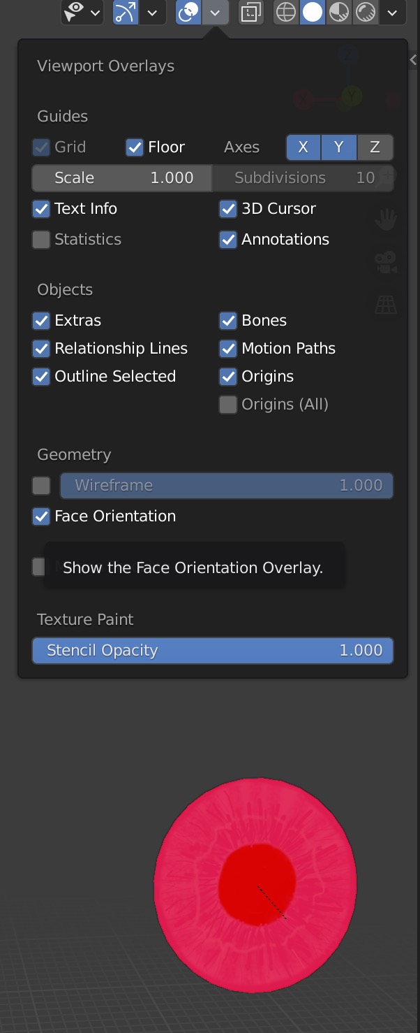
Once you have duplicated the eye, see section below), texture painting on one iris will mirror onto the other eye's iris.
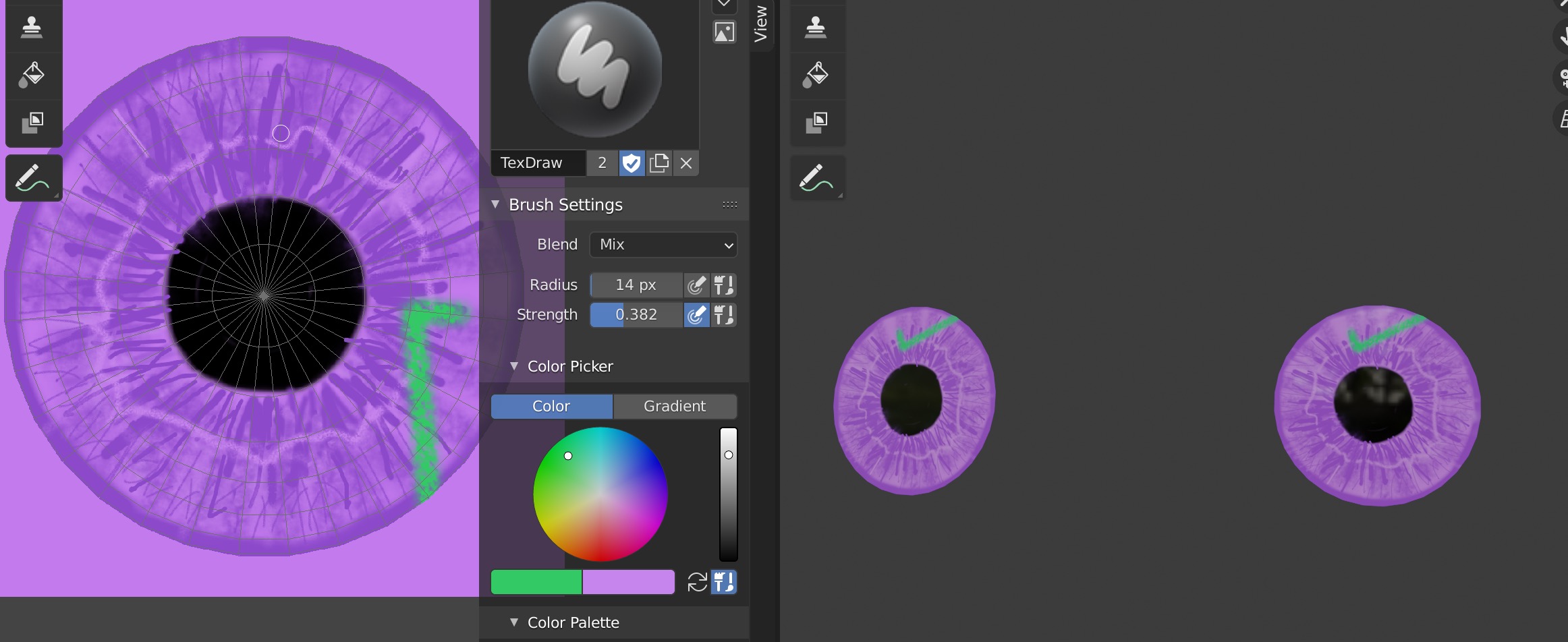
Painting the Sclera
The sclera is simply an all white image.
Painting the Cornea
The cornea is actually an image acting as a transparency mask: we paint white where we want transparency to be 1.0 which is the maximum, and black which is zero transparency.
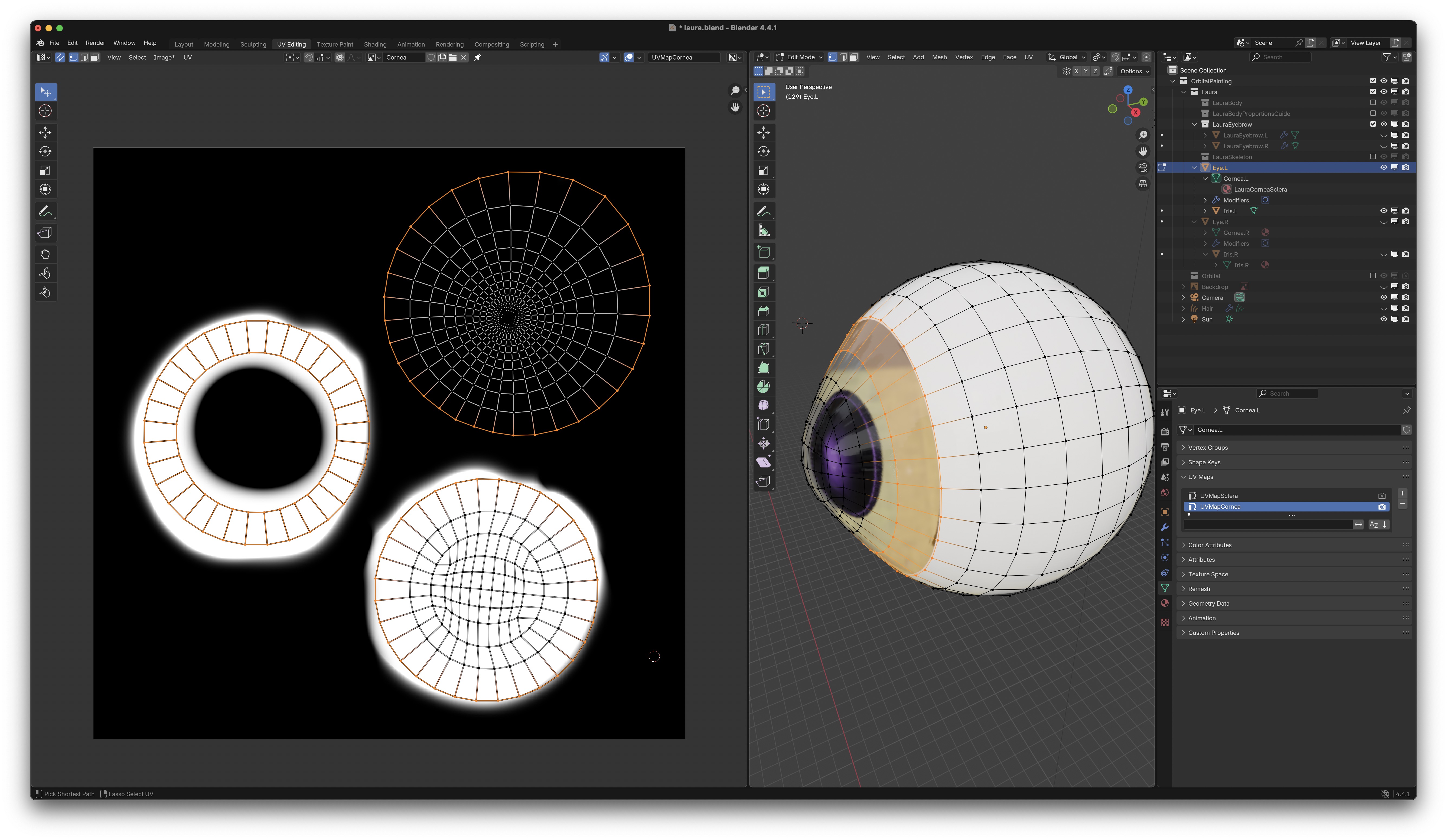 Then go to the Texture Paint tab and paint the transparent area.
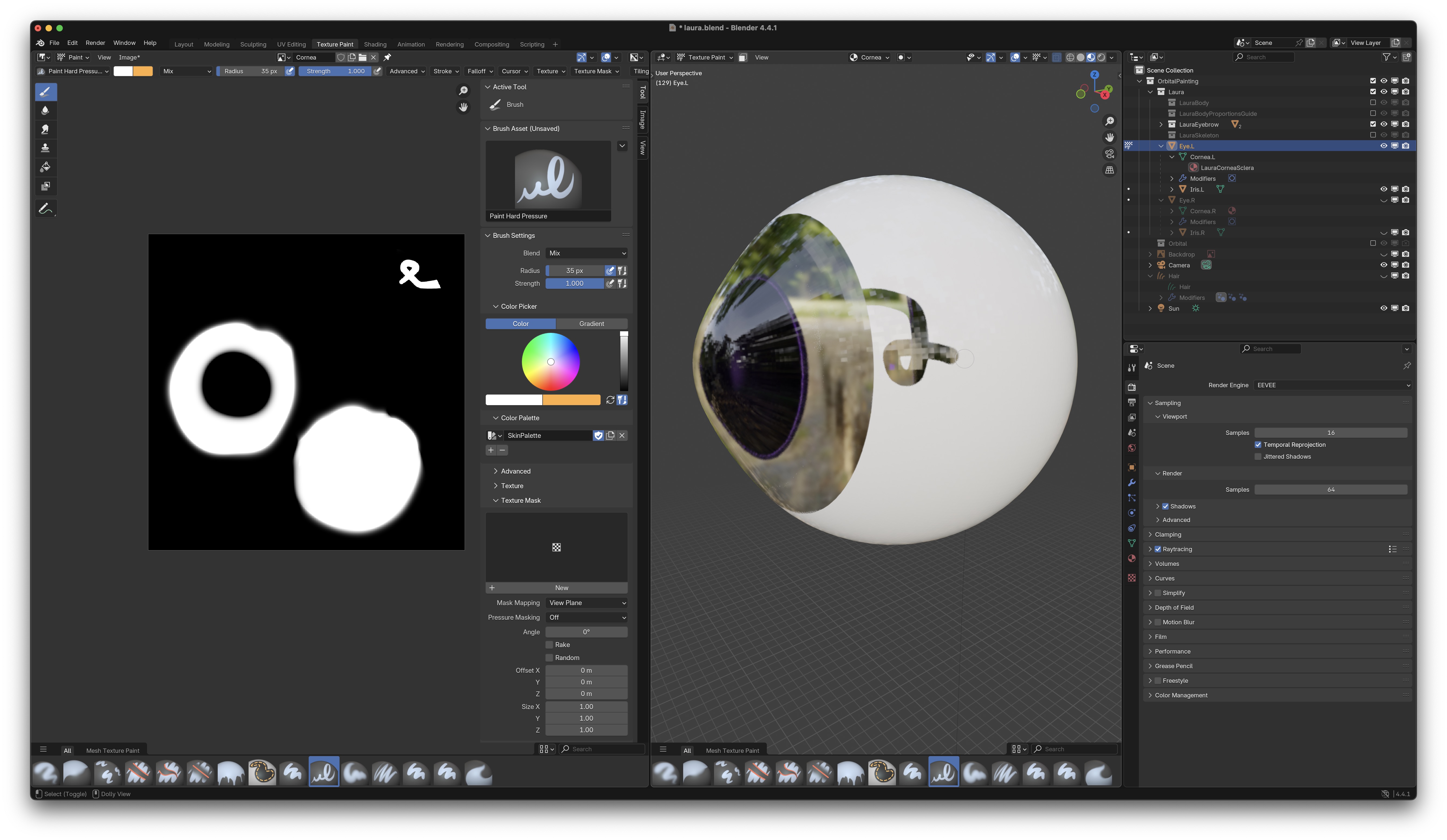
Parenting Iris to Cornea
To tie the iris in place to the cornea, Select the iris (child object) first, Shift Select the parent object (Cornea) next, then do Ctrl-P keep transform
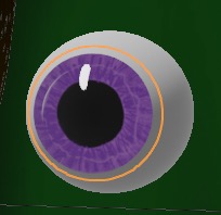
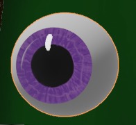
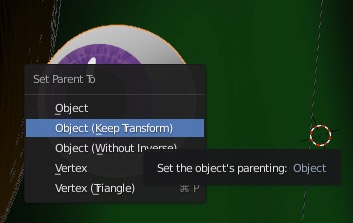
The relationships show up hierarchically in the outline view:
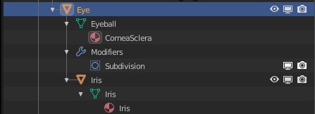 Finally, move the eye to the figure with M
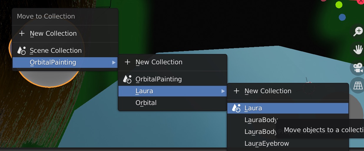
Duplicating Eyes
Duplicate the eye using Shift D and move it over out of the way of the first eye.
Rename the eyes to mark the left eye with .L and the right eye with .R. This will help with rigging later.
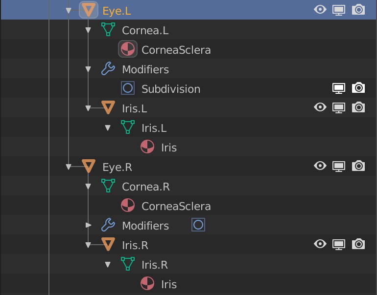
Rigging Eyes
Look at how we do torso rigging
Create two new eye bones with Shift A. Go to bone properties and leave Deform
off because we don't want the bone to change the eye shape.
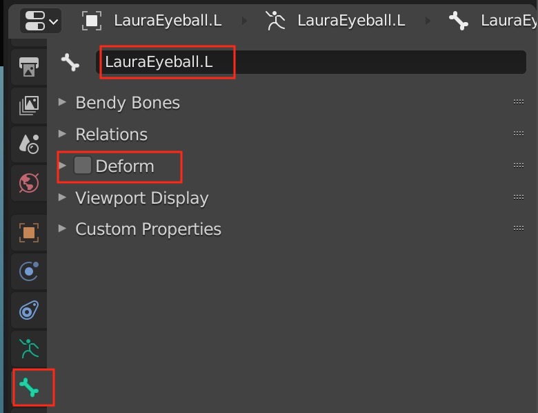 Then Select the eyeball object and Shift Select the bone for the eye.
Keep the transform.
Then Select the eyeball object and Shift Select the bone for the eye.
Keep the transform.
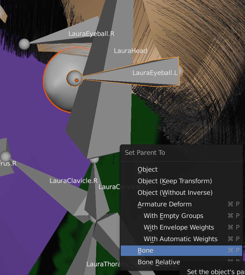
![]()
Do the same for the other eyeball.
Torso Rigging
We'll want to create a skeleton for the figure and pose it by moving the bones. First view Complete Character Rigging by Lee Salvemini and also Jonathon Williamson's Blender Cookie tutorial, Introduction to Character Rigging
To create the rig, I first do Shift A to create a single root bone and move it between the feet. This will position the whole figure.
Then selecting the root bone in edit mode, duplicate it using Shift D and move it up to the pelvis to be the first bone in the spine.
Next use E to extrude the second bone in the spine, and so on for all the bones including the head bone.
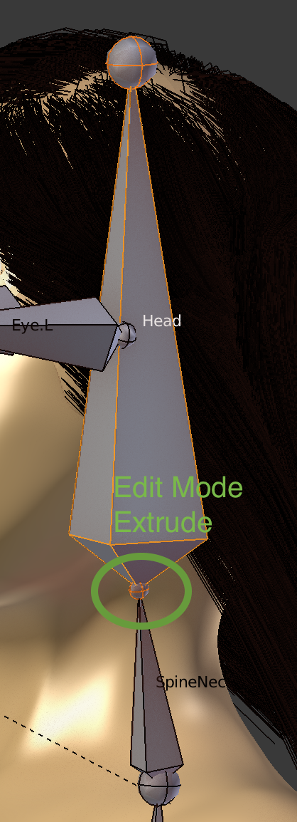 For the left arm bones, duplicate the top spine bone with Shift D and move it into position to be the clavicle.
Do similarly for the left leg bones, duplicating the bottom spine bone.
Rename all the arm and leg bones on the left side, and add the suffix .L
Copy the left side bones and move to the right. Now, selecting the right side bones, do W Flip Names to change all the names to the .R
suffix.
For the left arm bones, duplicate the top spine bone with Shift D and move it into position to be the clavicle.
Do similarly for the left leg bones, duplicating the bottom spine bone.
Rename all the arm and leg bones on the left side, and add the suffix .L
Copy the left side bones and move to the right. Now, selecting the right side bones, do W Flip Names to change all the names to the .R
suffix.
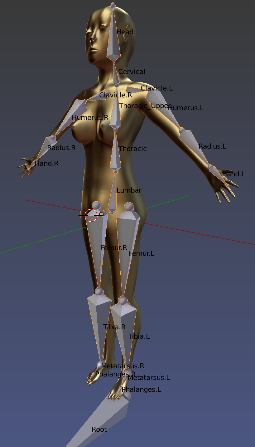 Now we do a bit of clean up and parent the two clavicle bones to the thoracic upper spine bone.
Go into Pose Mode, shift select both clavicle bones and finally the thoracic bone, then parent
with Ctrl-P keeping the relative bone offset (so one bone doesn't automatically connect to the end of the other bone).
Now we do a bit of clean up and parent the two clavicle bones to the thoracic upper spine bone.
Go into Pose Mode, shift select both clavicle bones and finally the thoracic bone, then parent
with Ctrl-P keeping the relative bone offset (so one bone doesn't automatically connect to the end of the other bone).
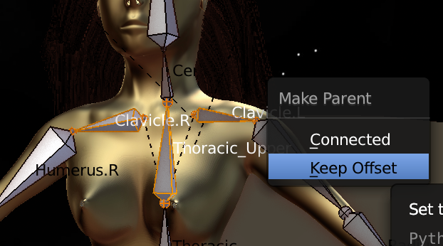 parent both femurs to the lumbar spine bone,
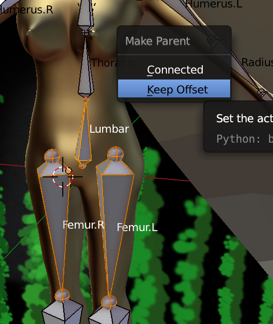 Parent the entire body armature to the root bone,
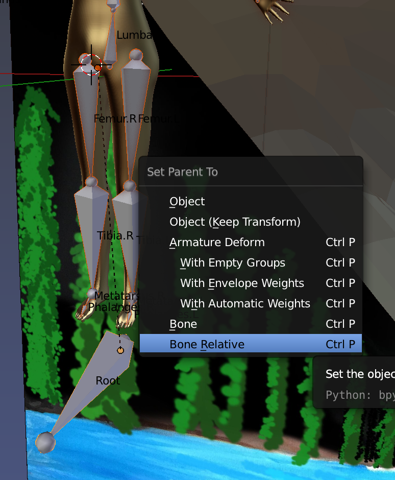 For the root bone, we just want it to move the body rig, not deform the mesh, so we unset deform,
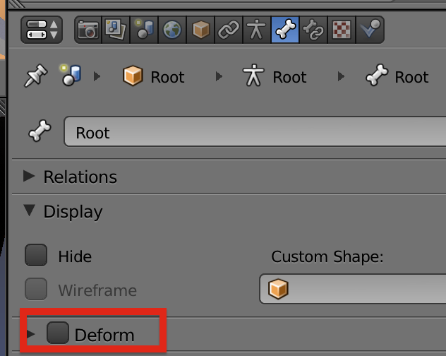 The bones are chained in child/parent relationships,
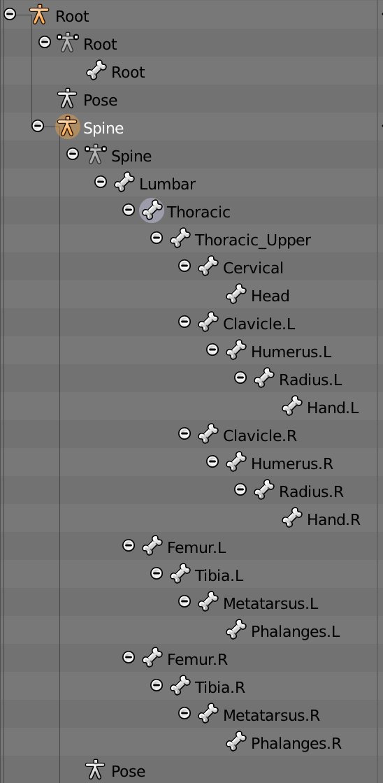 By duplicating bones with Shift-D, we keep all the bones as part of one single object even though they are not directly connected to each other.
Torso Skinning
Go into object mode, click on the mesh, then shift click on the armature, then Ctrl-P with automatic weights to tie the mesh to the armature.
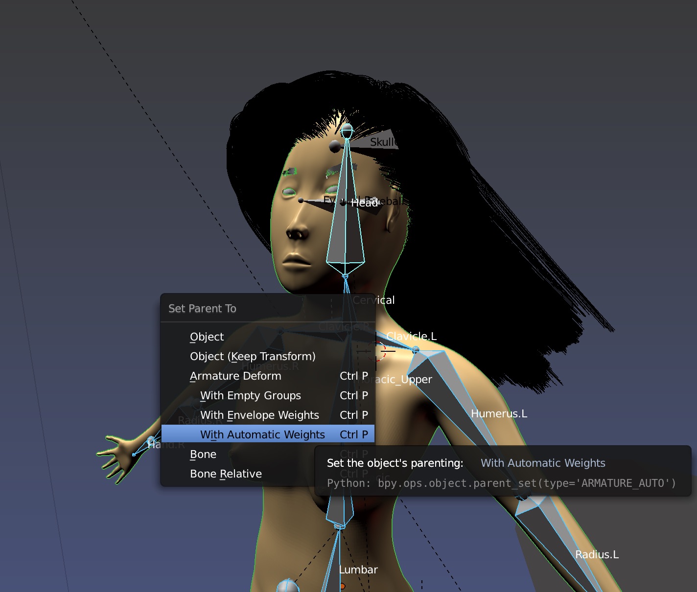 You'll see new vertex groups in the mesh controlled by the bones in the armature.
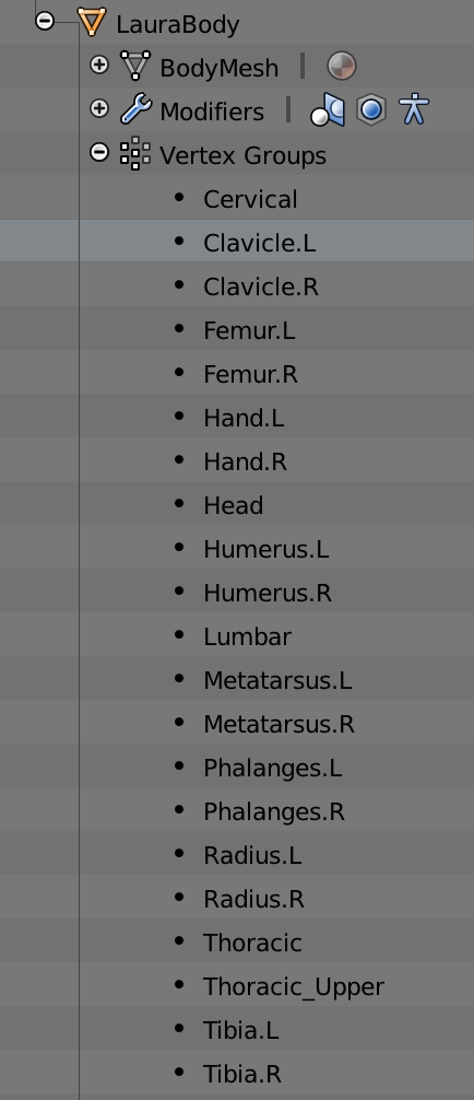
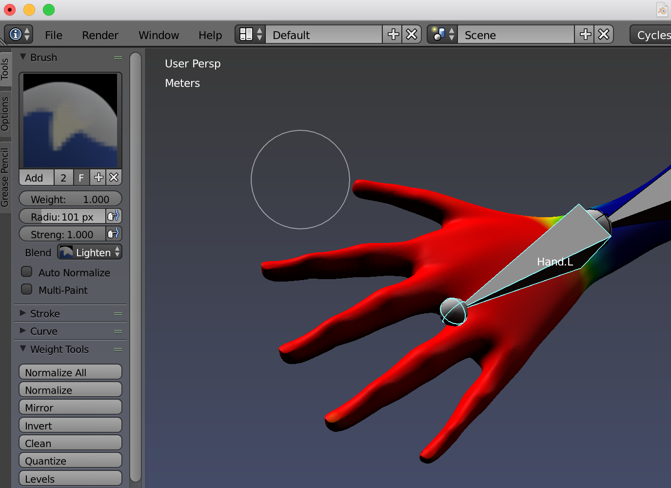
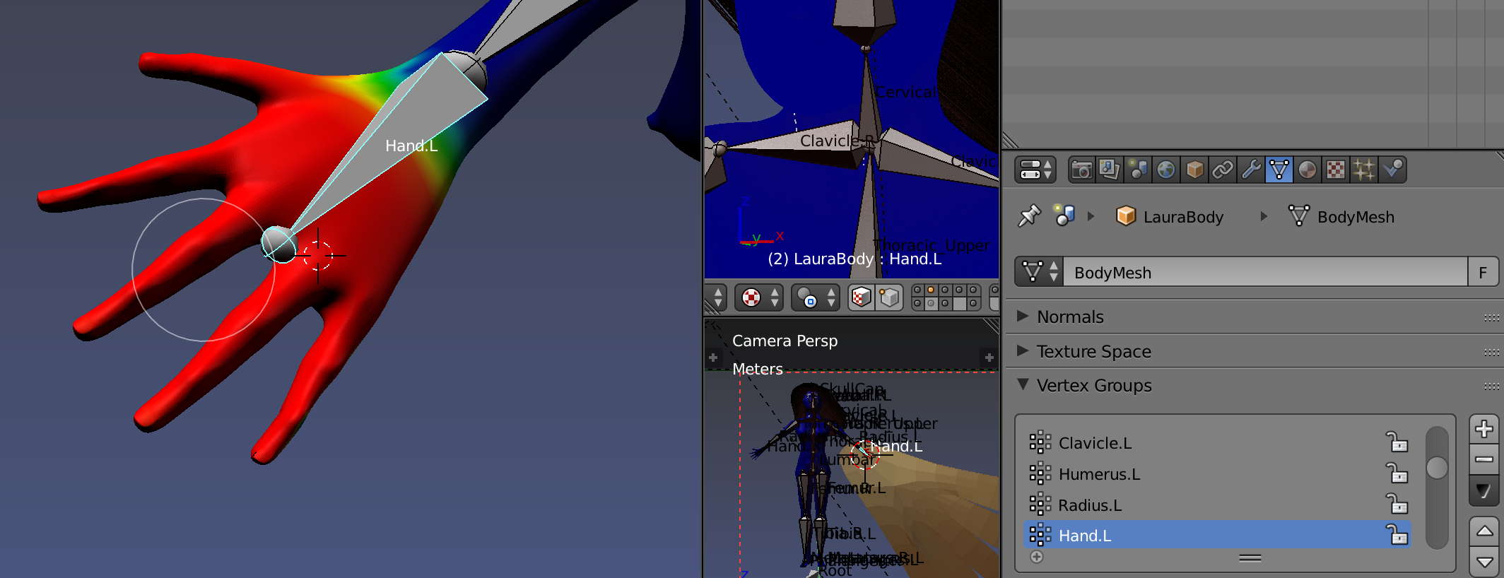
Now go into Pose Mode and move the hand bone. You'll see the mesh of the hand move also.
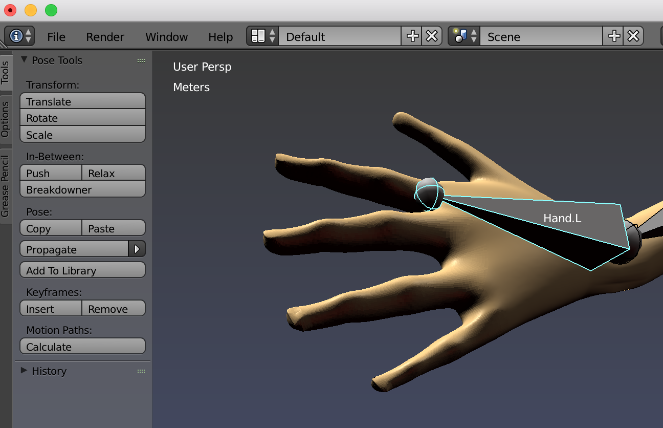
Be sure to weight paint all parts of the hand or you'll see this when moving the bone,
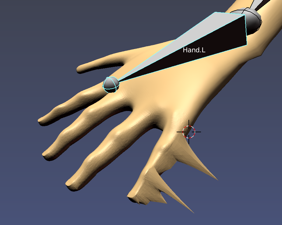
Torso Posing
Select the rig and hit m to move all the bones to their own layer,
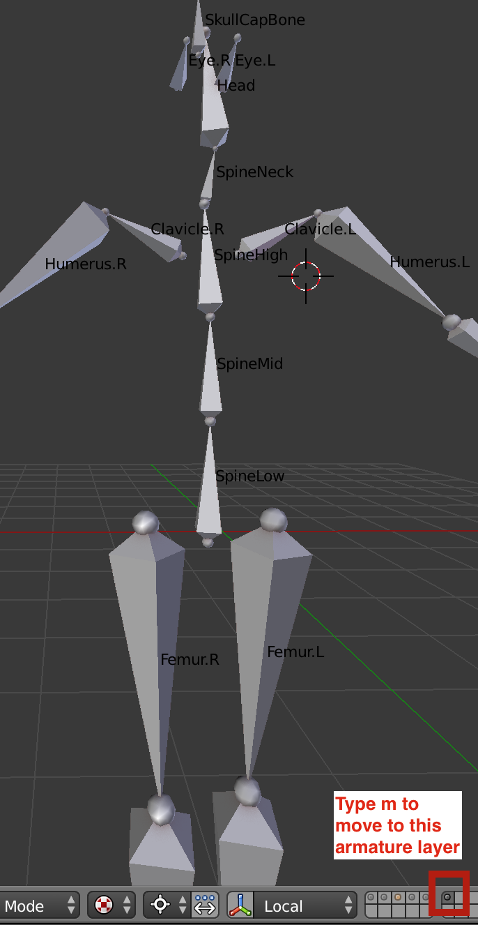
You can adjust the pose in pose mode and keep the new pose as the resting pose,
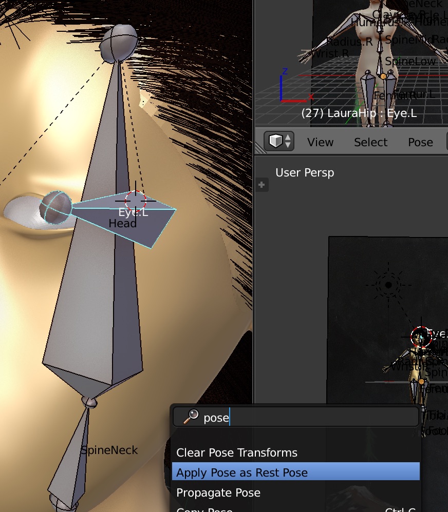
You may need to reset the armature to its resting position,
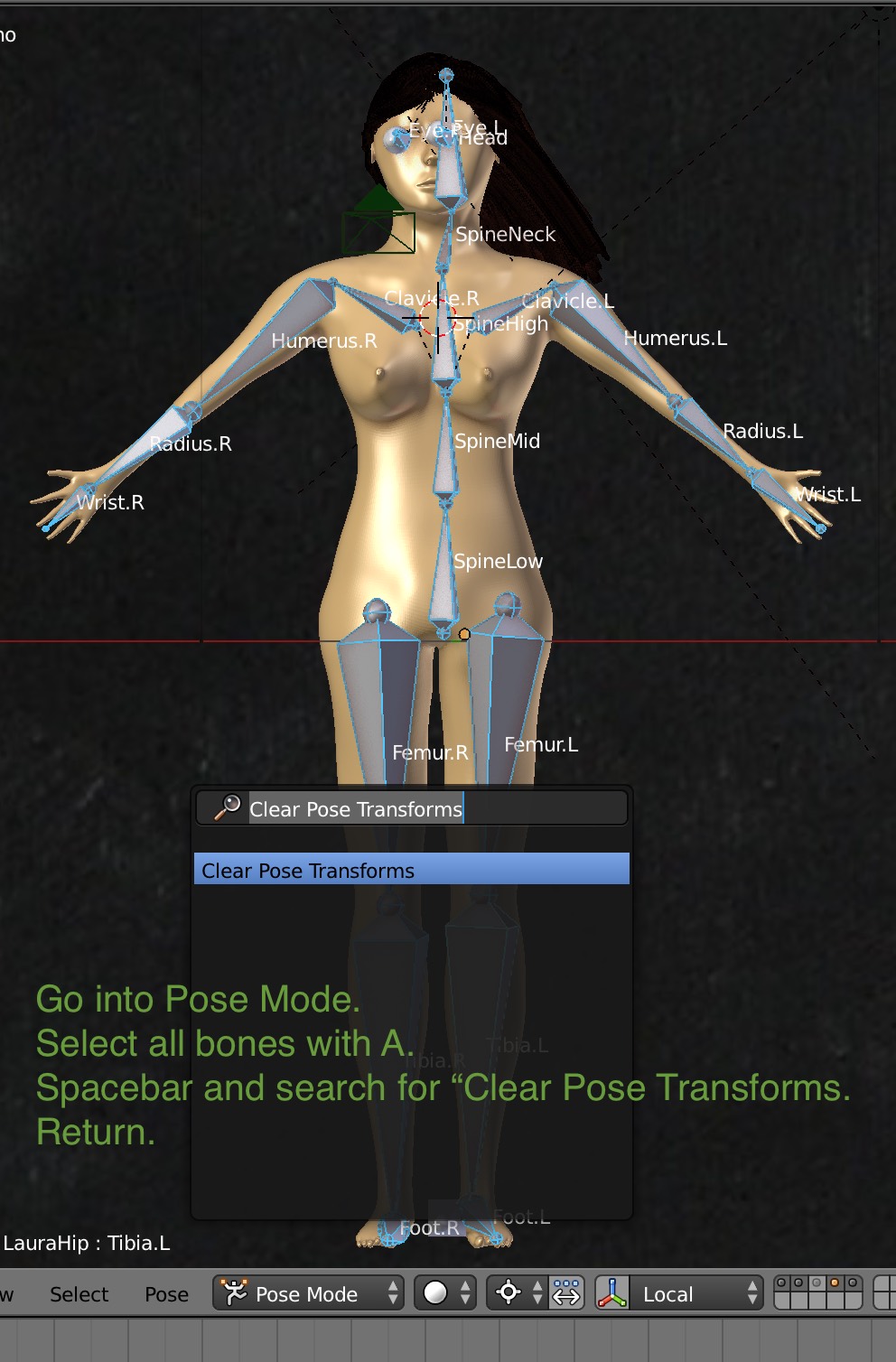
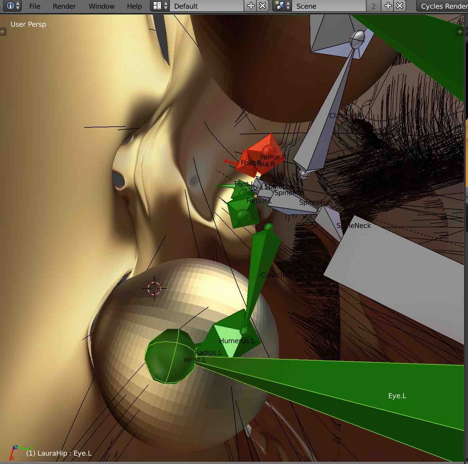
Here's an example of what you can do with the rigging. I switched to pose mode and moved the head bone with G to tilt
the entire head, eyes, hair and all. Then did a test render.
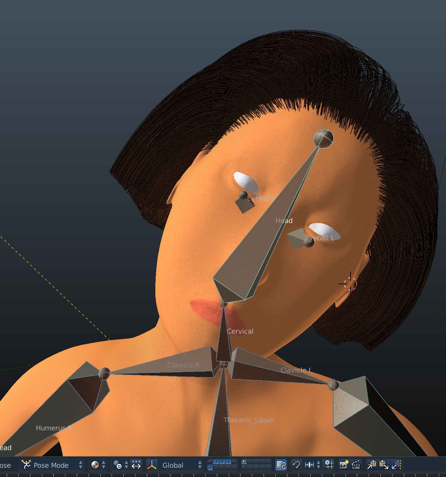
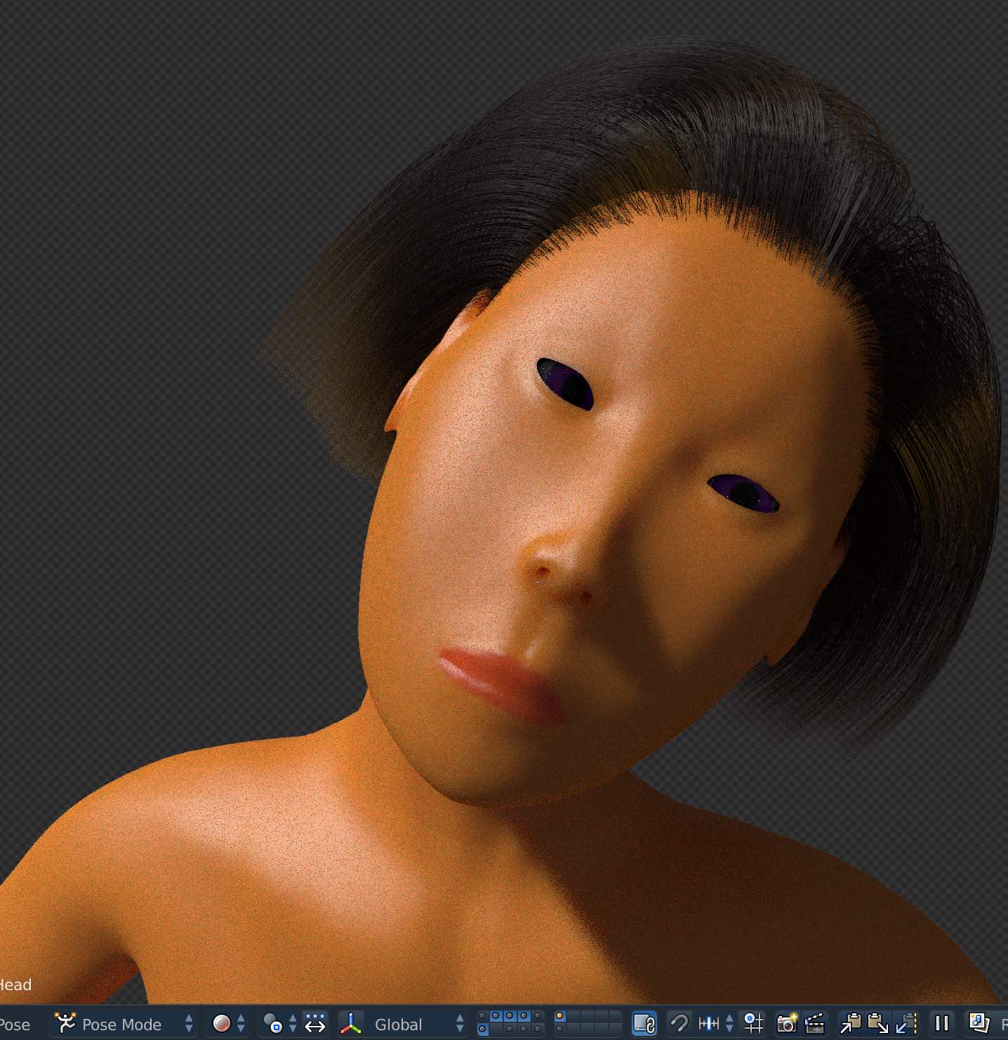
Large Objects: an Orbital
We are going to input a huge object: an orbital. It's a ring with radius r = 1.5 x 10⁶ km
Spin up the orbital to a 24 hour day/night cycle and check the acceleration,
r ω2 = 0.808639 g, which is comfortable for us Terrans.
The side walls are 500km up, the trees are 100km tall, and the base of the orbital is 400km wide.
Create the orbital with Shift A select mesh torus. Rotate it 90 degrees.
 Apply the rotation factor to the object with
Ctrl A ➤ Apply Rotation and Scale
so the rotations return to 0 and the torus lines up with the coordinate axis in its rotated position.
Apply the rotation factor to the object with
Ctrl A ➤ Apply Rotation and Scale
so the rotations return to 0 and the torus lines up with the coordinate axis in its rotated position.
![]() Finally, we want the torus origin to be it's center, not the bottom, so bring up the tools with T and select Origin to Geometry.
The yellow object center dot will shift from bottom to middle.
Finally, we want the torus origin to be it's center, not the bottom, so bring up the tools with T and select Origin to Geometry.
The yellow object center dot will shift from bottom to middle.
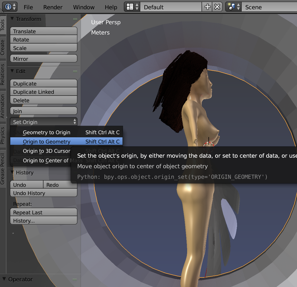
Checking Backface Culling will help you view the mesh better as you edit it to remove the inner rings. Also you can select the seam in the middle
with Alt Shift Select and dissolve
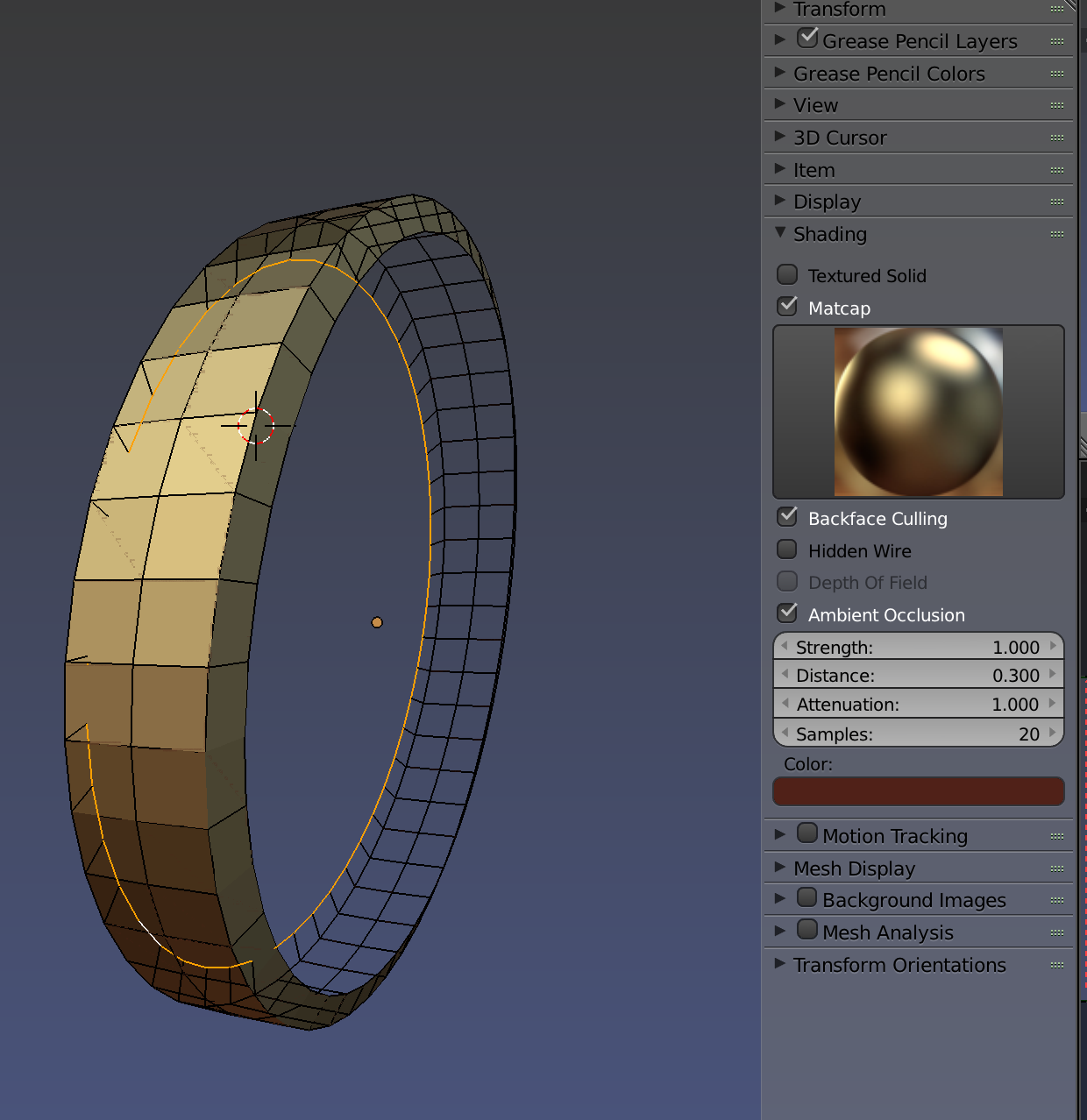 To see the orbital, you need to greatly extend the clipping end range
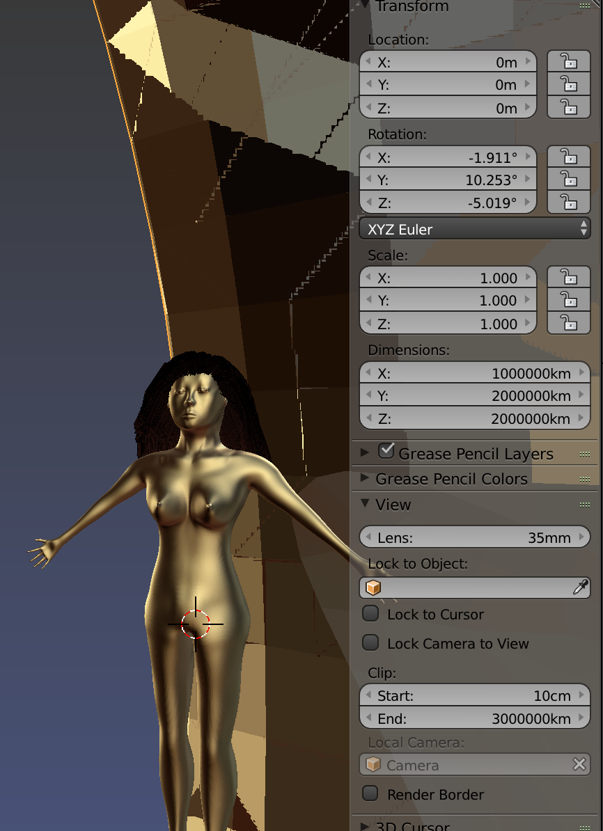 Finally, enter in the dimensions of the orbital and translate it upwards in z by the orbital radius so that the female figure is positioned near the bottom inner surface.
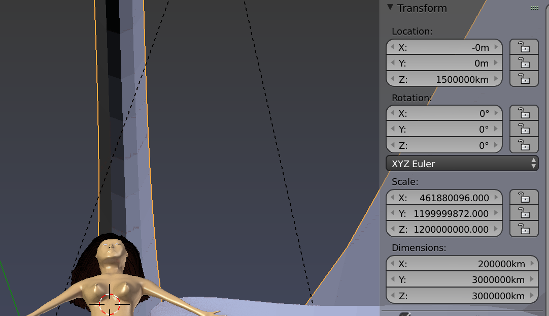 As you zoom out to see the huge orbital, you may lose the female figure.
Select the figure and hit space bar view selected to find it.
As you zoom out to see the huge orbital, you may lose the female figure.
Select the figure and hit space bar view selected to find it.
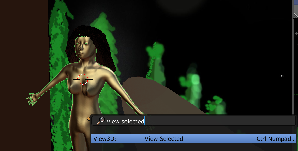 The same goes for zooming out to see the orbital, with the origin marked near the bottom,
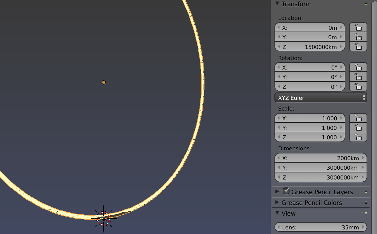
Trees
Who doesn't like trees? Please see this three part tutorial series Blender Smoothie: How to Create a Realistic Trees I'll go through a worked example for a painting I'm working on.
Creating Leaf Images
Before we begin, let's create the leaf images: one of the leaf with transparent background; the other of an alpha mask having a black background with solid white for the leaf.
I captured a photograph of a leaf, then using the free Photoshop equivalent Gimp, I did File ➤ Open As Layers to import images of leaves, on image per layer.
Next add an alpha (transparency) channel to each layer using the menu
Layer ➤ Transparency ➤ Add Alpha Channel
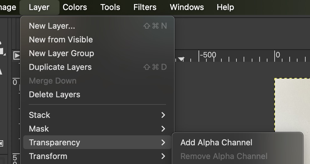
You can now use the Eraser Tool to erase the background to transparent. Or you can do it another way by flood filling and painting the background to a solid color (blue) first.
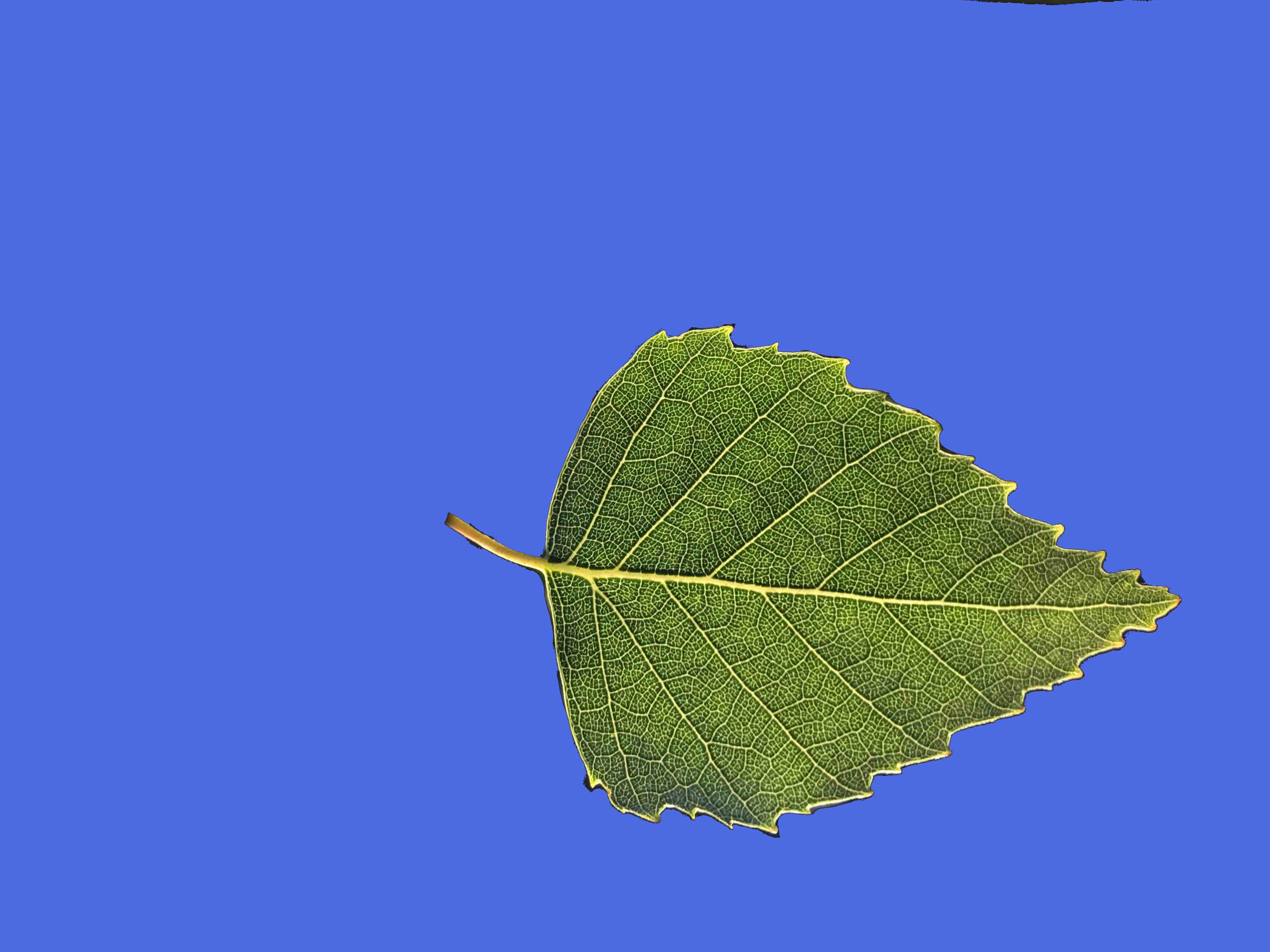
Then to erase the background, do Colors ➤ Color To Alpha. A menu will come up.
You will use the eye dropper tool to select the blue background color, then say OK to make the background transparent.
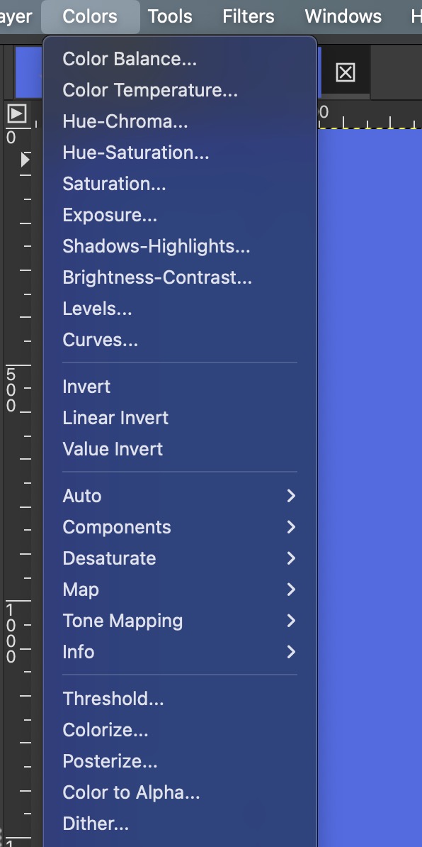
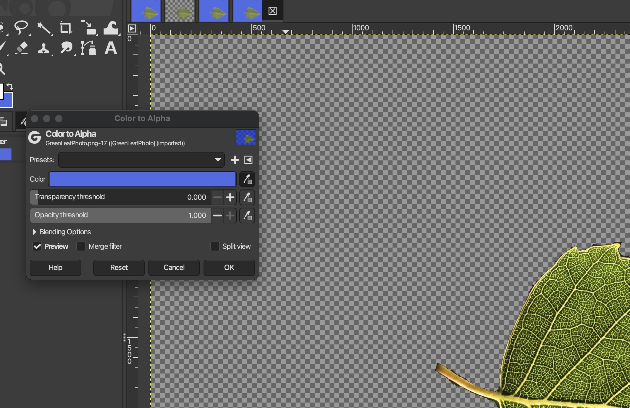 Now the foreground is the leaf and the background has alpha = 0.
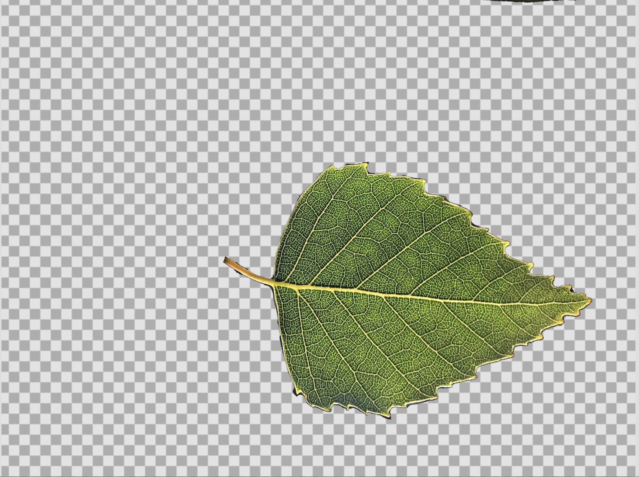
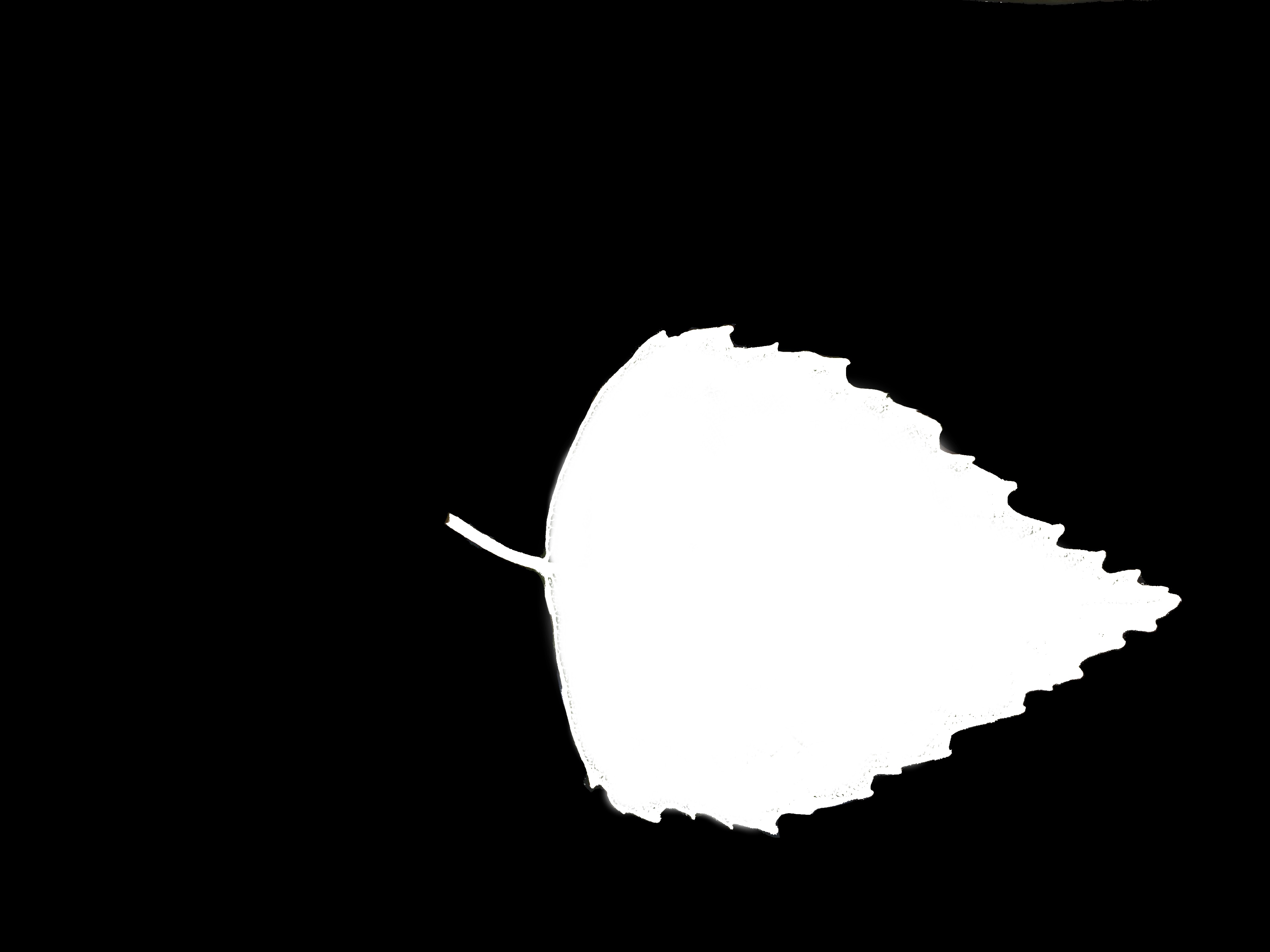
Sapling Tree Generator
First you'll need to activate the Sapling add on by clicking the checkbox,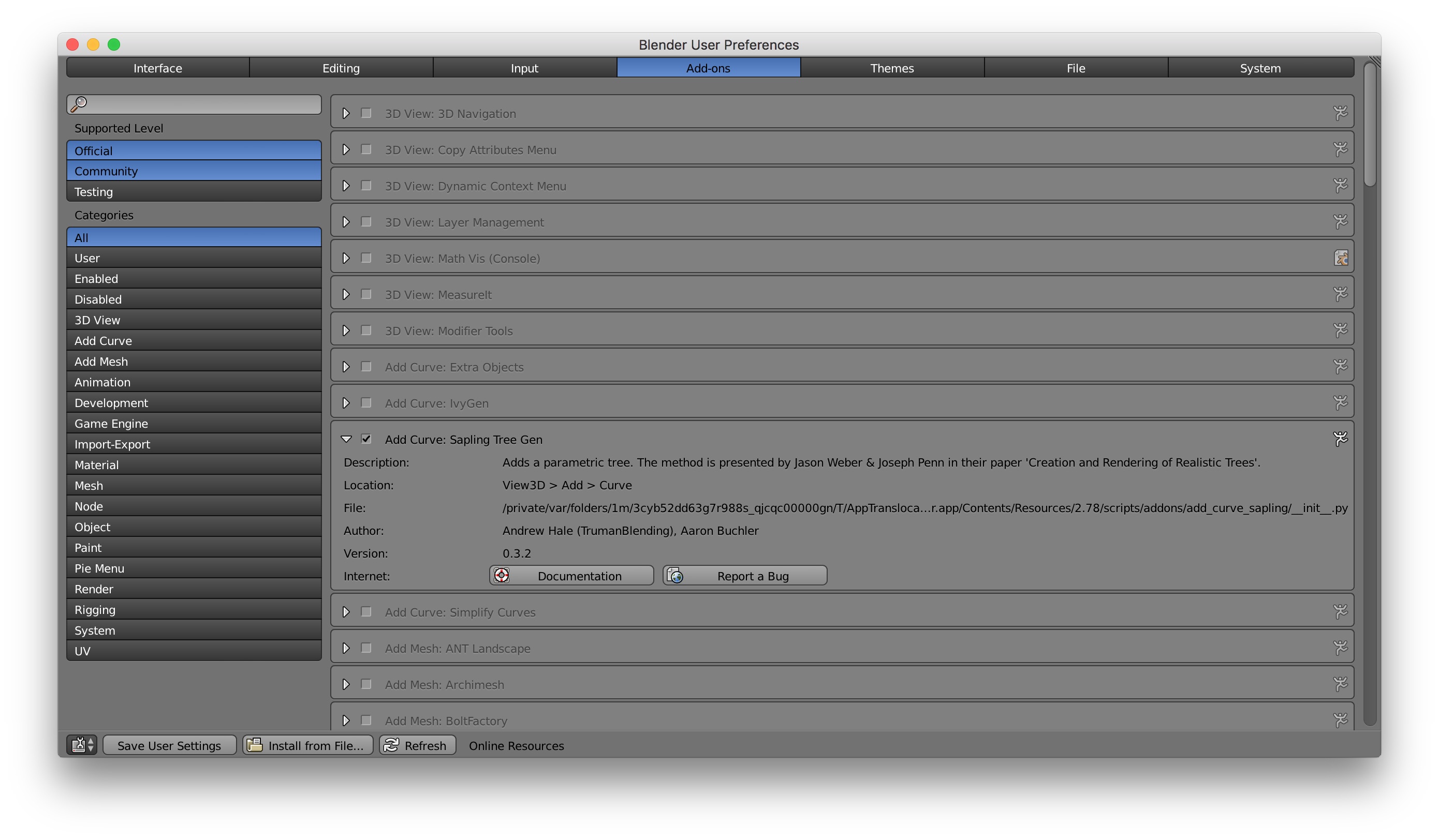 Sapling is a python program which generates a tree model as a series of curves.
It's located in the directory
Sapling is a python program which generates a tree model as a series of curves.
It's located in the directory
To add the tree, do T to get the tool window, then do Shift A and select curve/sapling,
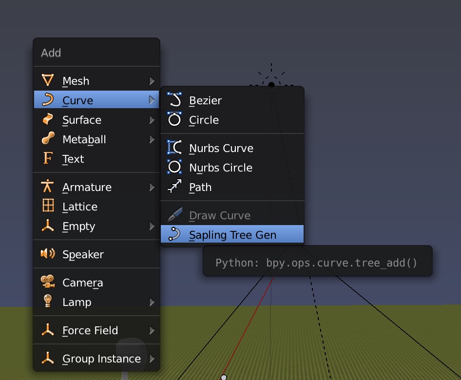 You'll see the tree outline and the settings appear in the toolbar.
I'm going to load the Callistemon preset tree type in the toolbar,
You'll see the tree outline and the settings appear in the toolbar.
I'm going to load the Callistemon preset tree type in the toolbar,
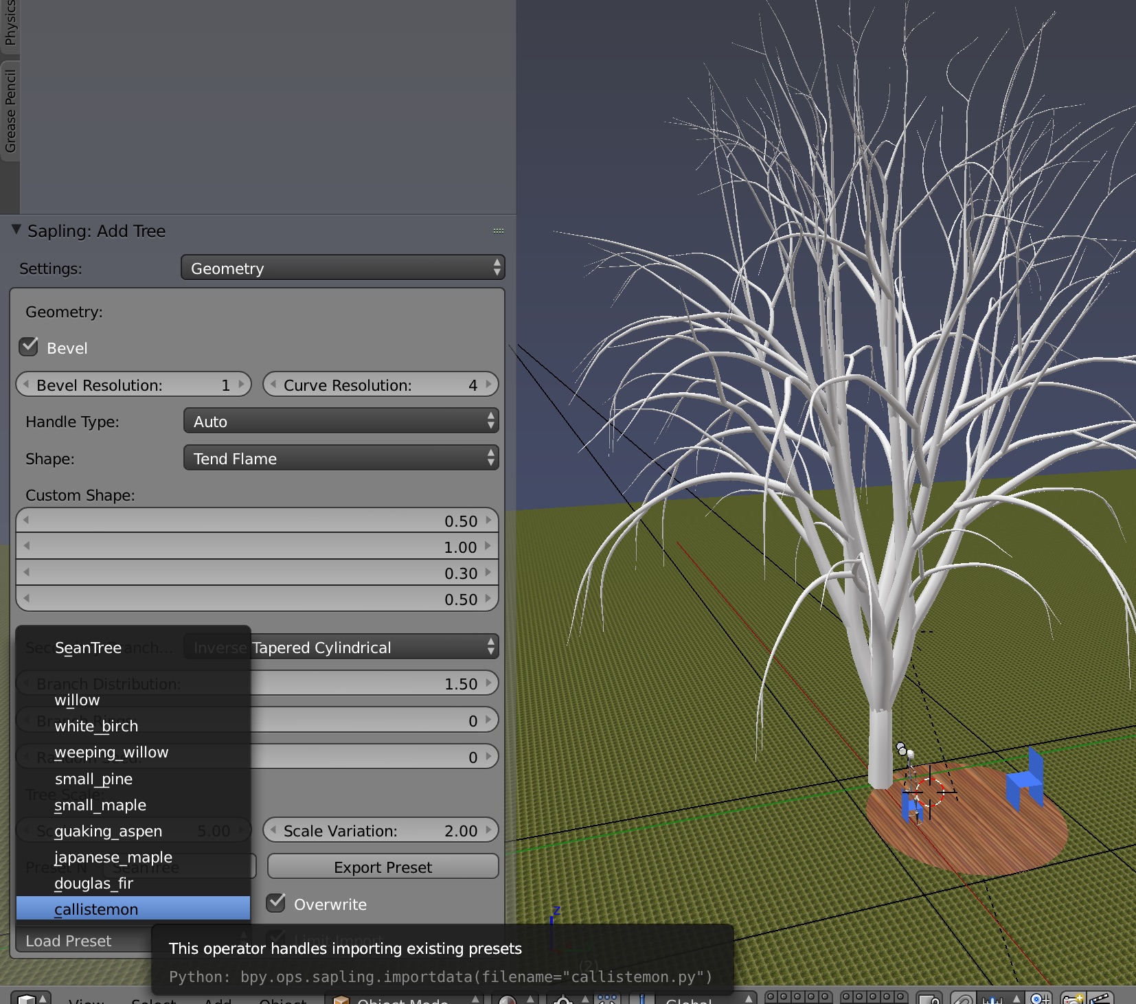 In the tree settings in the toolbar, set the bevel to 4 so the trunk isn't square,
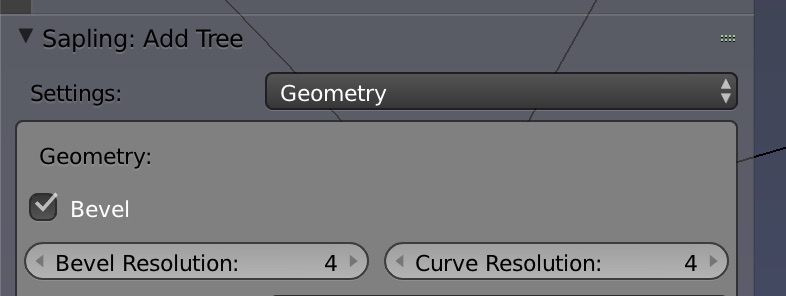 There's lots of settings. Try adjusting the tree scale, the number of branch splits, branch lengths,
random seed, leaf scale, etc.
Use a nonzero vertical attraction because branches grow upwards.
You can click a box to show the leaves,
There's lots of settings. Try adjusting the tree scale, the number of branch splits, branch lengths,
random seed, leaf scale, etc.
Use a nonzero vertical attraction because branches grow upwards.
You can click a box to show the leaves,
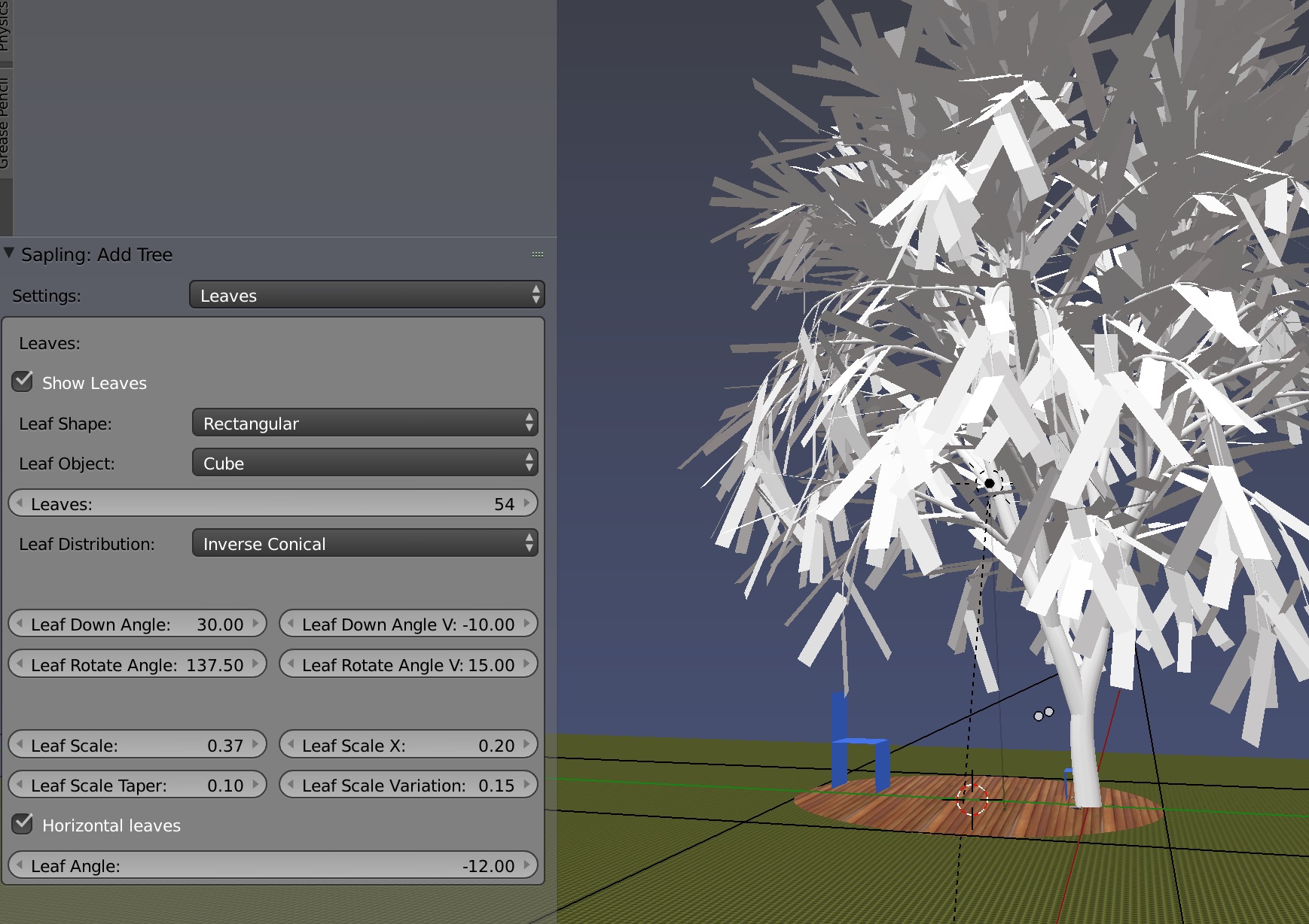 If you move the tree, the tree settings go away.
As soon as you are done with your tree design, name your tree and save it
in export presets,
If you move the tree, the tree settings go away.
As soon as you are done with your tree design, name your tree and save it
in export presets,
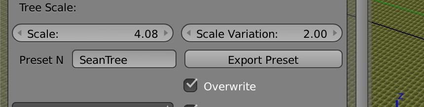 At this point the tree is all curves. You can move it around and scale it.
The next step is convert curves to a mesh with Alt C.
Be aware this will slow down viewing and rendering considerably.
At this point the tree is all curves. You can move it around and scale it.
The next step is convert curves to a mesh with Alt C.
Be aware this will slow down viewing and rendering considerably.
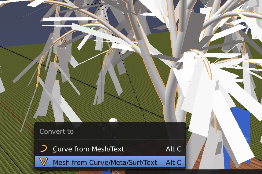 We will separate out the trunk. Shift select vertices on the trunk,
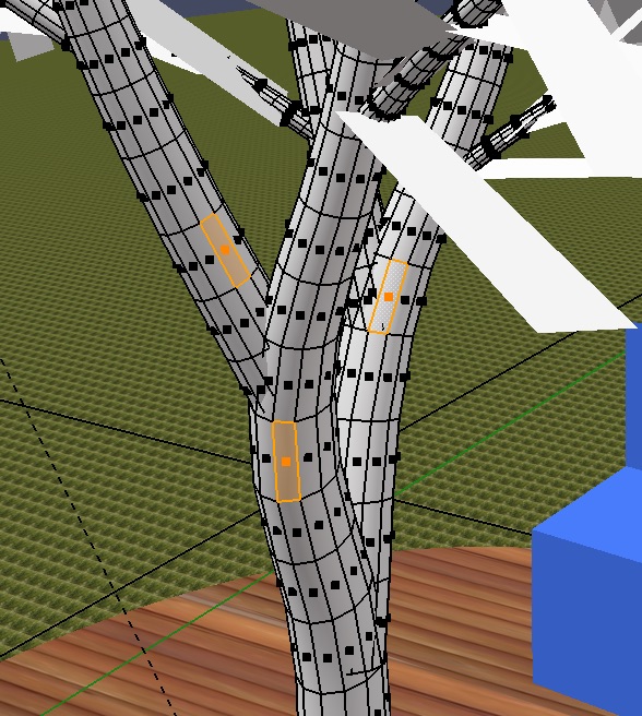 then Ctrl L to select connected vertices,
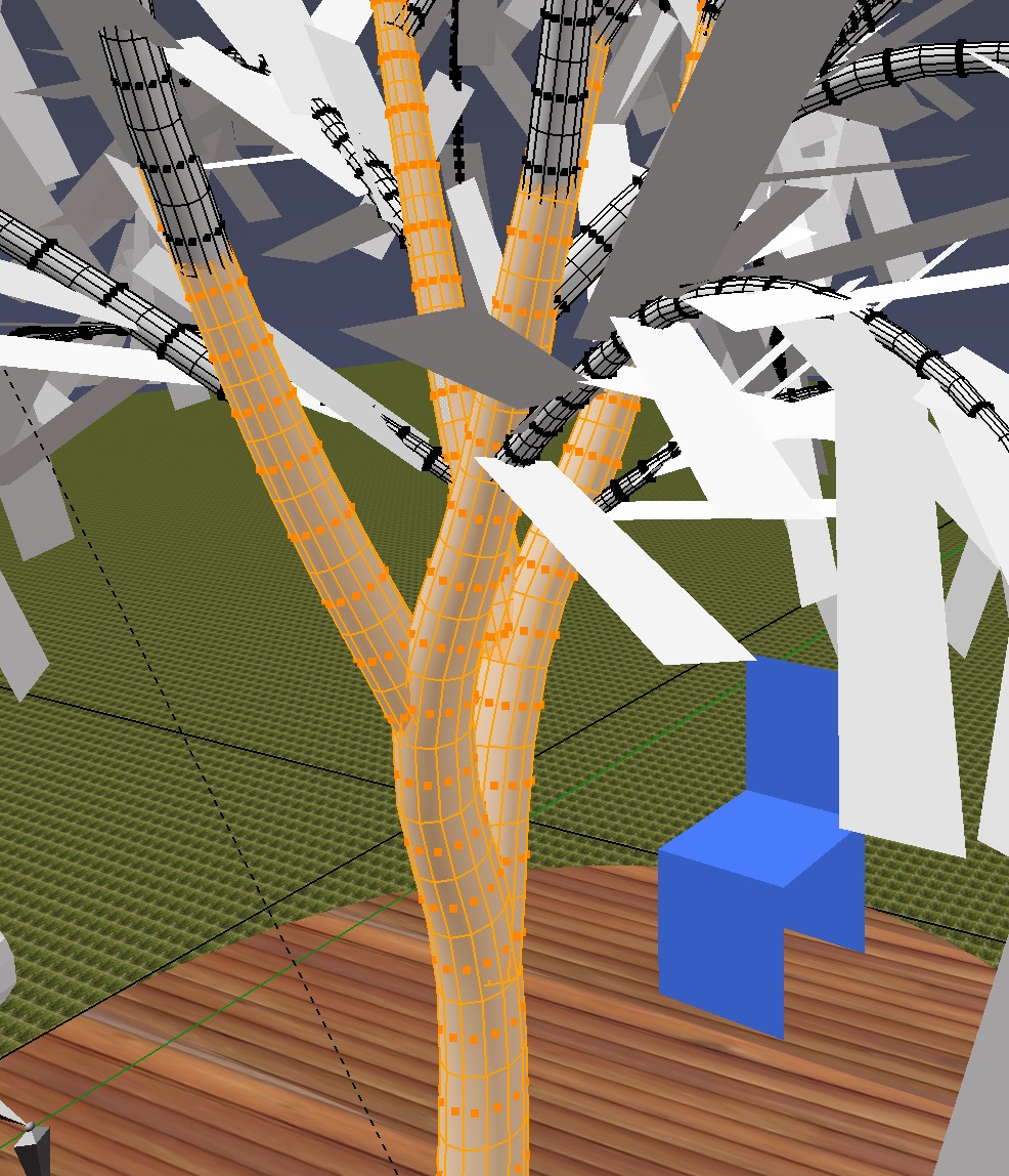 Then P choose separate by selection to separate the trunk mesh from the branches mesh.
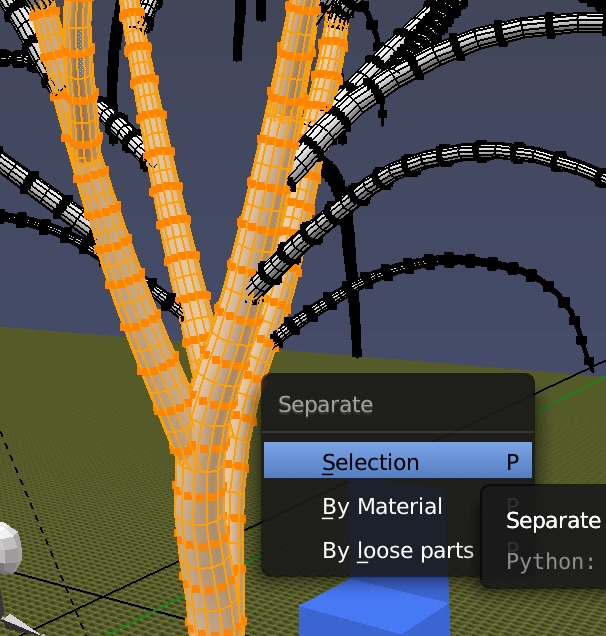 Obtain an image of tree bark,
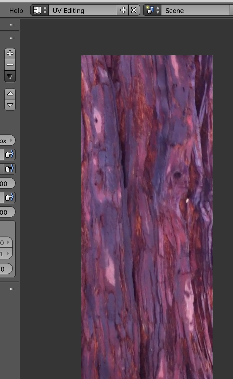 Now go into UV Editing, select the trunk, go into edit mode,
Shift Alt Select a a few edge loops and mark them as seams with Ctrl-E Mark Seam.
Now go into UV Editing, select the trunk, go into edit mode,
Shift Alt Select a a few edge loops and mark them as seams with Ctrl-E Mark Seam.
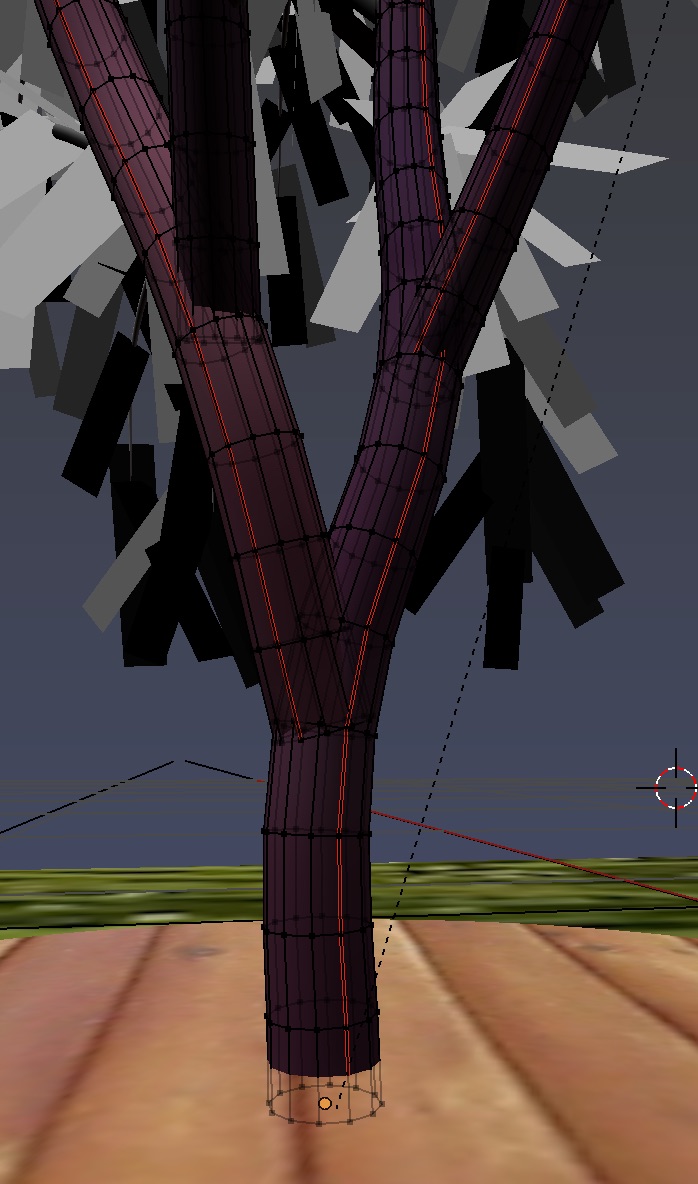 Select all the vertices with A, do u to UV unwrap.
Load the tree bark image. Now resize and position the mesh on the image.
You can let uv mesh extend beyond image, it will repeat.
Select all the vertices with A, do u to UV unwrap.
Load the tree bark image. Now resize and position the mesh on the image.
You can let uv mesh extend beyond image, it will repeat.
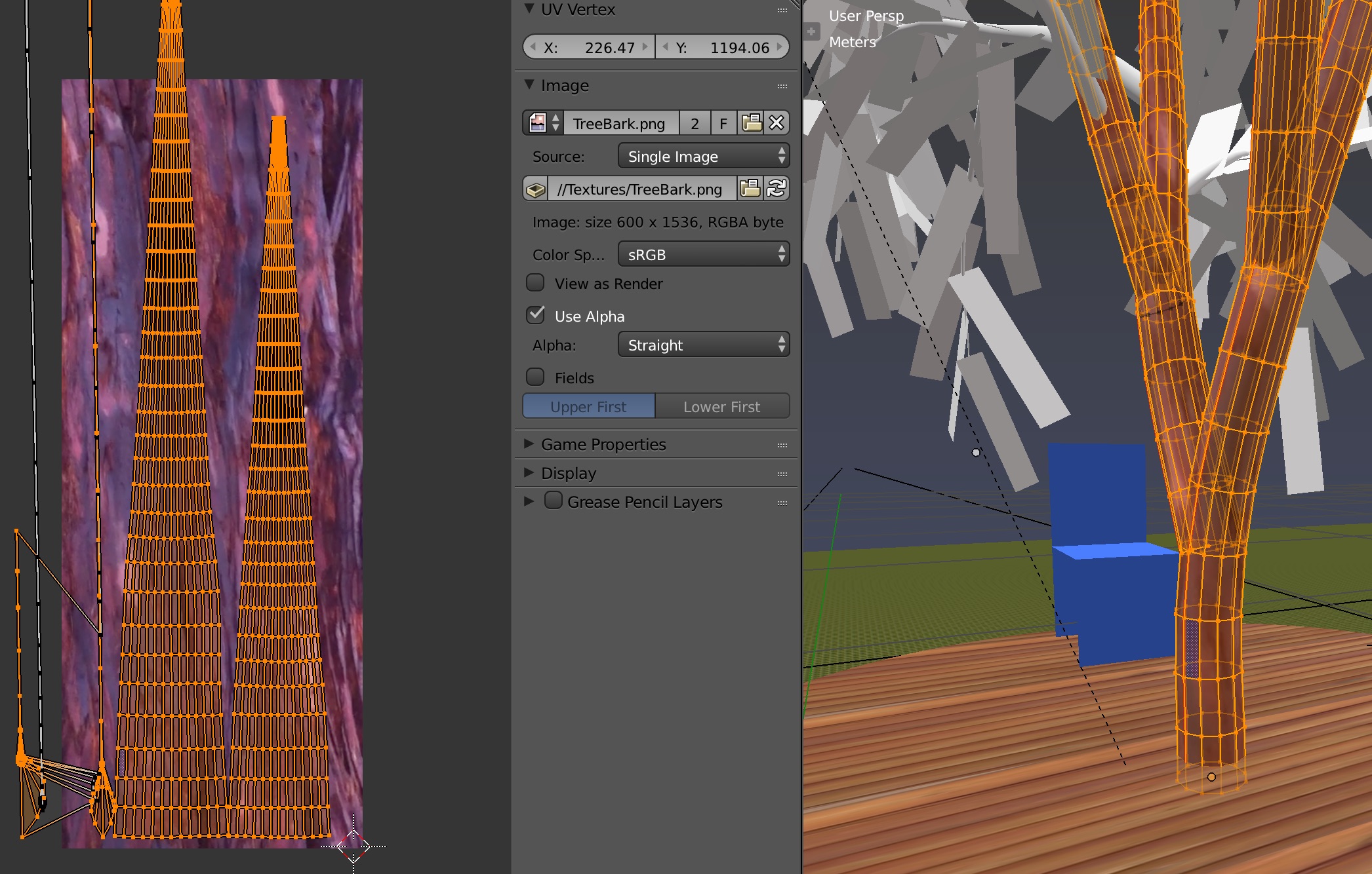 Go back to Compositing, select the trunk and create a new material.
Use the tree bark as texture image in UV mode,
Go back to Compositing, select the trunk and create a new material.
Use the tree bark as texture image in UV mode,
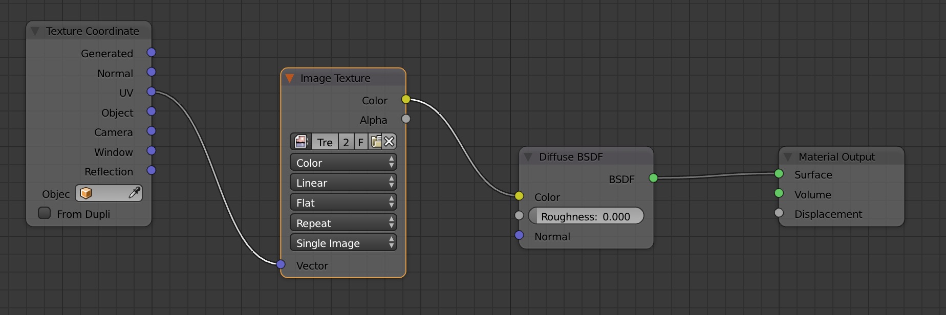
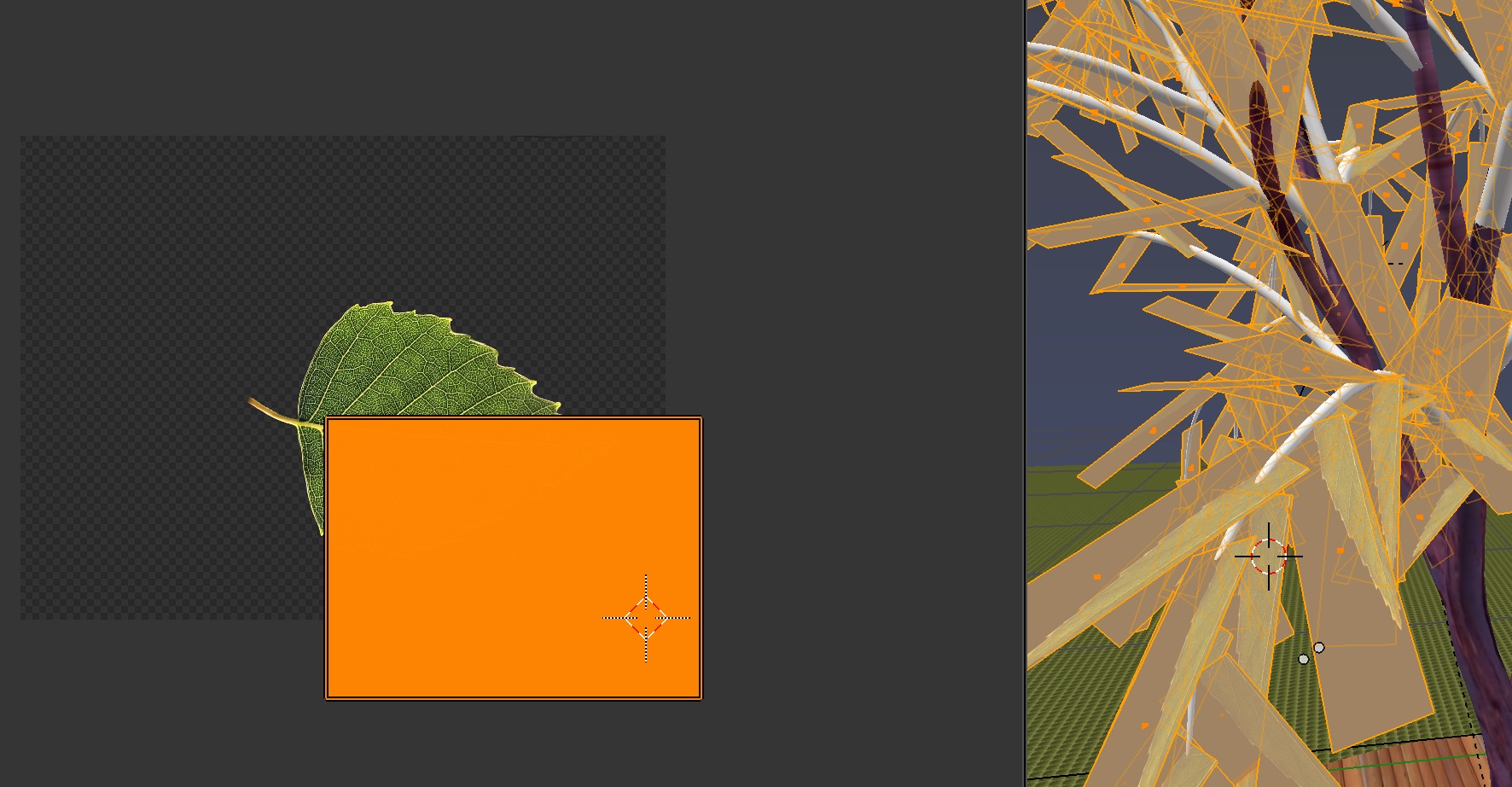 Here's the final mapping and how it looks on the leaves in both mask mode and image mode,
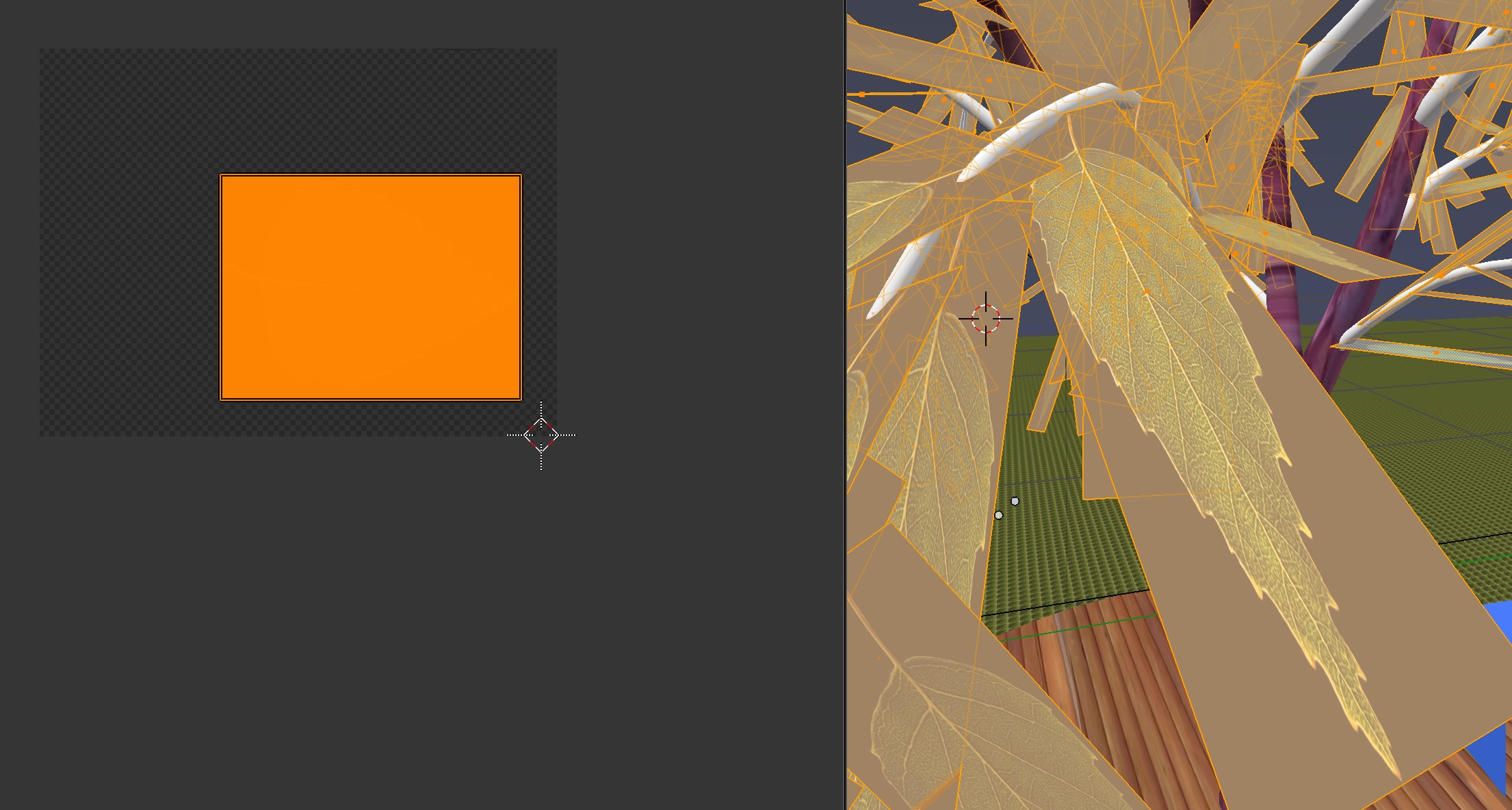
 Now go into Compositing and create new nodes with Shift A.
The leaf image feeds into the diffuse BDSF shader and the leaf alpha mask feeds into the mix shader.
Now go into Compositing and create new nodes with Shift A.
The leaf image feeds into the diffuse BDSF shader and the leaf alpha mask feeds into the mix shader.
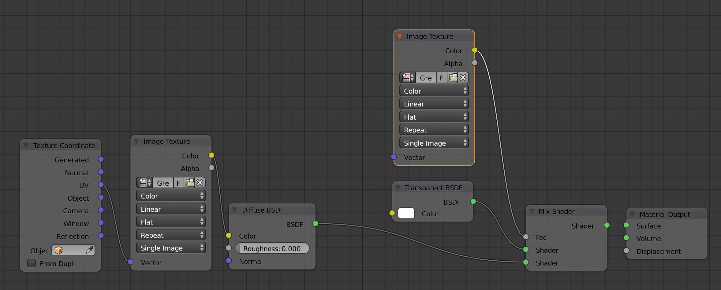 One more thing, to avoid showing the leaf background as white in the viewport, dial down the alpha setting in the materials pane,
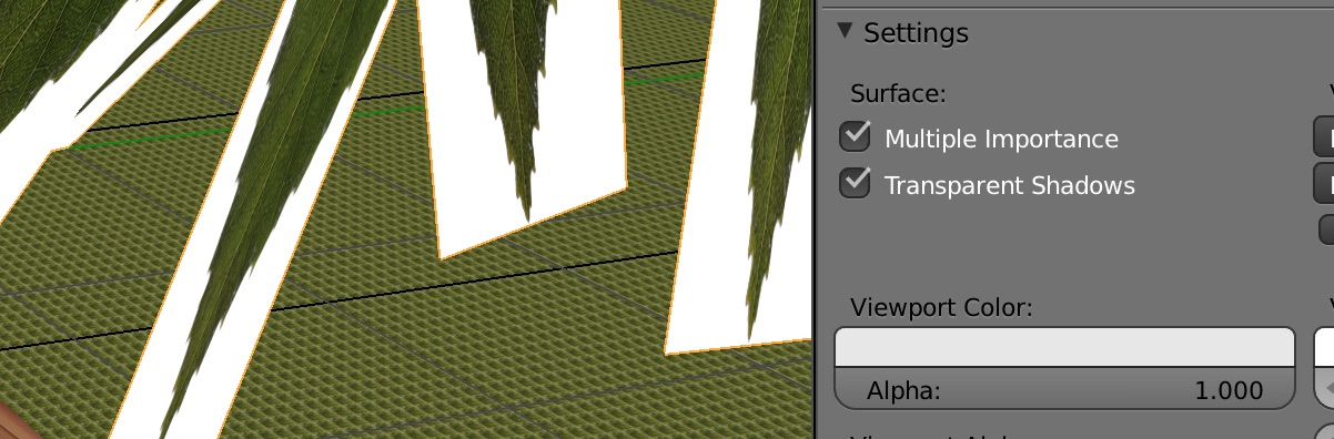
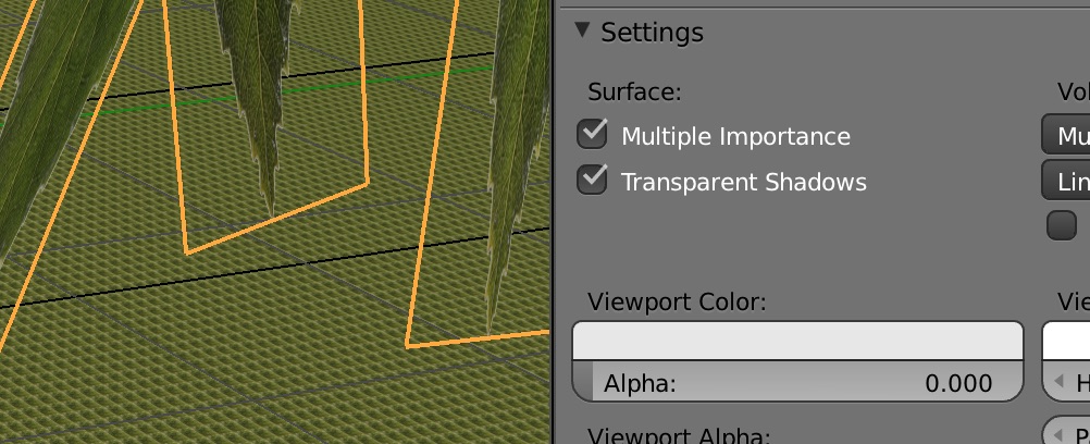 Do a test render,
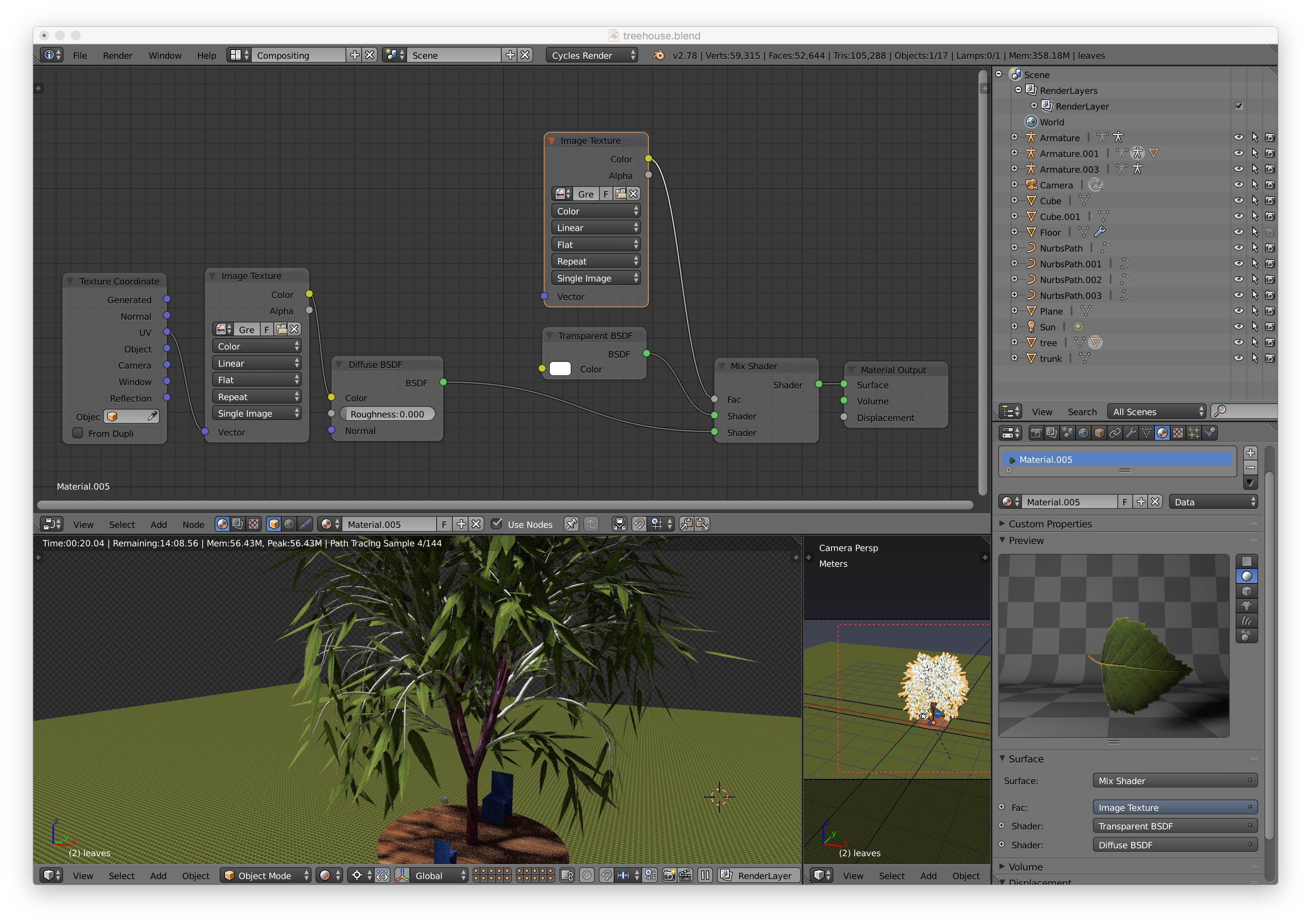
Leaves on Deck
We'll use the particle system to spread leaves all over the floor of the treehouse.
Select the object which hosts the particles. Properties Editor->Particle Properties Select Hair, not emitter. Render Properties Render As Object. Object->Instance Object->Eyedropper, then select donut in 3D viewport Or create a new collection, add your objects to the collection, then in the above, Render As Collection instead. Scale, Scale Randomness. Click on Advanced. Enable Rotation. Randomize Phase and phase. Particle Properties->Use Count. Increase the count to sample those objects more from the collection. Object Data Properties (mesh)-> Vertex Groups. Add Group. Particle Properties->Vertex Groups->Density Add Group. 3D Viewport Weight paint mode. Brush blue = 0 density, Red = 1 (highest) density. You’ll see the donuts rearrange their positions to avoid blue and attract to red. Particle Settings Click off TV monitor icon to hide the particles to speed up.
Fence
Now let's do a fence using the array modifier. First create a segment of the railing by adding
a Nurbs curve with
Shift A
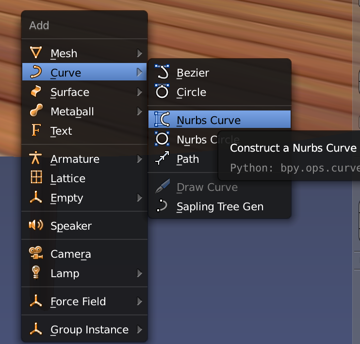 Go into Edit mode and shape it with the control points.
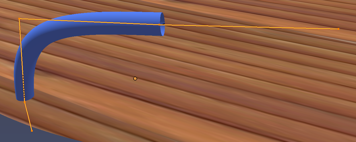 The main properties we'll use for now are Bevel to add thickness and create a tube instead of wire,
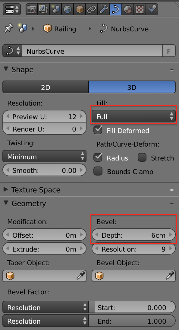 Clear the object's rotation and scale to defaults (zero angles, scale = 1) with
Ctrl A ➤ Apply Rotation and Scale
This is because the array modifier uses offsets based on rotation and scale of the object.
Set the object’s origin to the geometry using Shift Ctrl Alt C Geometry to Origin.
The object’s (0,0,0) is the
center of the object, bounding box center, I think? You'll see it marked with a small yellow dot.
Now create an Empty object using Shift A Empty Plain Axes.
Clear the empty's rotation and scale to defaults (zero angles, scale = 1) with
Ctrl A ➤ Apply Rotation and Scale
Now some contortions to match the origins of both the empty and the curve.
Select the railing and move the 3D cursor to railing’s origin with Shift-S Cursor to Selected
Finally move the empty's origin to the 3D cursor to make empty and curve share the same origin by
selecting the empty
and using Shift-S Cursor to Selected Let's rename the empty to Railing Control
You should see something like this:
Clear the object's rotation and scale to defaults (zero angles, scale = 1) with
Ctrl A ➤ Apply Rotation and Scale
This is because the array modifier uses offsets based on rotation and scale of the object.
Set the object’s origin to the geometry using Shift Ctrl Alt C Geometry to Origin.
The object’s (0,0,0) is the
center of the object, bounding box center, I think? You'll see it marked with a small yellow dot.
Now create an Empty object using Shift A Empty Plain Axes.
Clear the empty's rotation and scale to defaults (zero angles, scale = 1) with
Ctrl A ➤ Apply Rotation and Scale
Now some contortions to match the origins of both the empty and the curve.
Select the railing and move the 3D cursor to railing’s origin with Shift-S Cursor to Selected
Finally move the empty's origin to the 3D cursor to make empty and curve share the same origin by
selecting the empty
and using Shift-S Cursor to Selected Let's rename the empty to Railing Control
You should see something like this:
![]() Now select the railing again and add an Array modifier. For its settings, let's pick a
Relative Offset
of x = 0.5cm, a Fixed Count of 5 to begin with and for the Object Offset
select the empty.
Now select the railing again and add an Array modifier. For its settings, let's pick a
Relative Offset
of x = 0.5cm, a Fixed Count of 5 to begin with and for the Object Offset
select the empty.
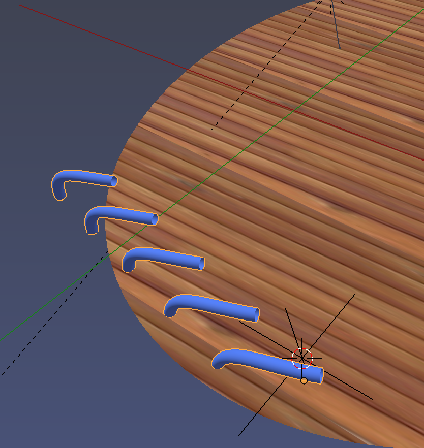 Now rotate the empty in z and increase the array fixed count. You'll see that each copy of the
railing object is offset by the empty's angle giving a circle,
Now rotate the empty in z and increase the array fixed count. You'll see that each copy of the
railing object is offset by the empty's angle giving a circle,
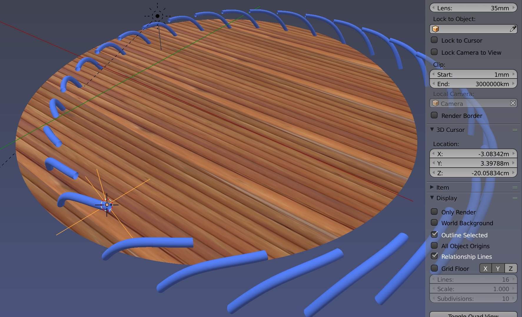 If you want to move this structure, remember to select both the curve and the empty simultaneously
with Shift Select
If you want to move this structure, remember to select both the curve and the empty simultaneously
with Shift Select
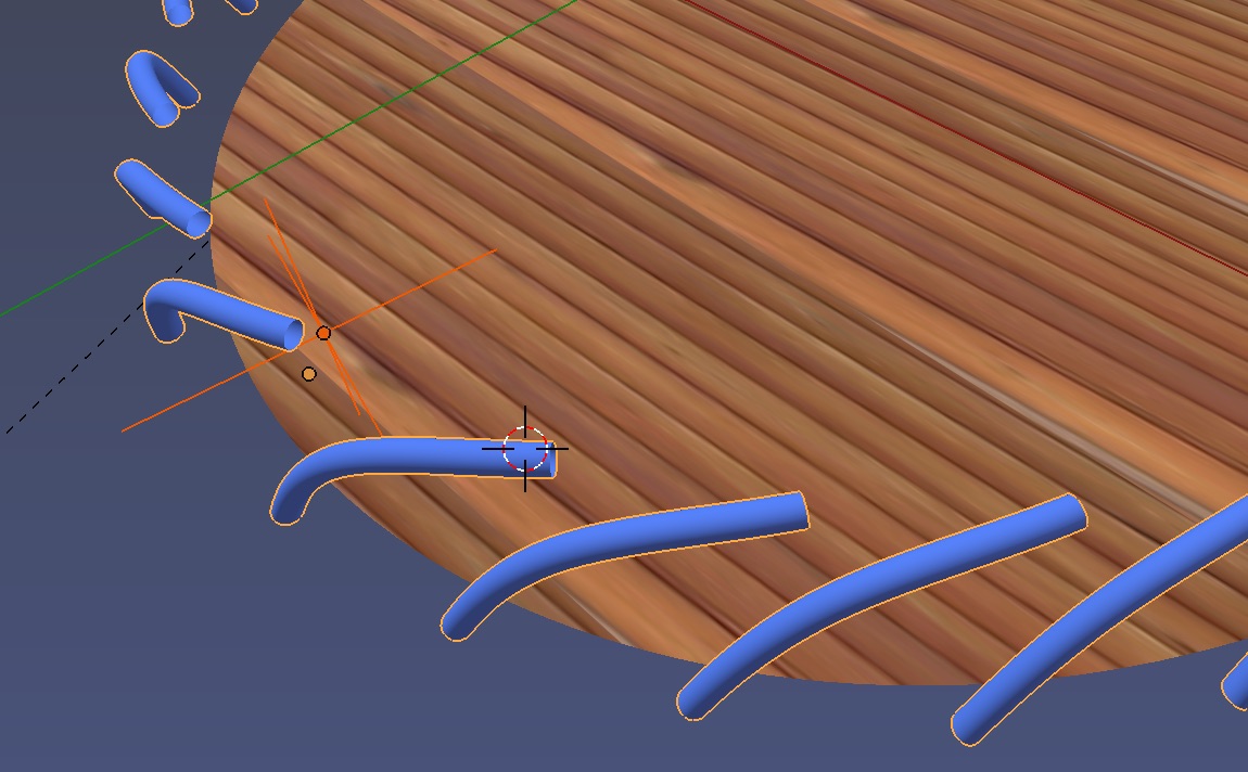 You can adjust the angle of the railing by selecting it, going into edit mode and rotating the base
element in z,
You can adjust the angle of the railing by selecting it, going into edit mode and rotating the base
element in z,
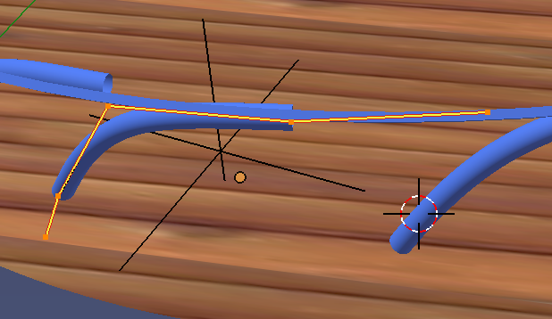
Mirror Ball
About the mirror ball... We can use the new principled shader for all materials. See Andrew Price's Blender Guru Presentation The main features are:
- Fresnel is built-in: glancing angles show mirror reflections correctly. What is Fresnel?
- Leave specular at the default 0.5 for IOR = 1.5
- Real materials are either metals (1) or dielectrics (0), not in between.
- Metals have reflection only. The metal reflection color is set in the specular tint. Diffuse materials don’t have specular tint.
- For glass and water: use metallic = 0, roughness = 0, transmission = 1, IOR = whatever
- Sheen and Sheen Tint is for fabric like velvet.
- Clearcoat. TBD.
- TBD Image Texture Node, set to Non-Color Data, feed into Metallic input in Principled BSDF node.
- For dielectrics, adjust roughness. This will automaticaly reduce Fresnel.
Wine Glass
We'll render a wine glass (with wine) using the glass liquid interface method. The key is to make sure all interfaces, air/glass, glass/water, and air/water have the correct index of refraction and (IOR) that the normals point in the correct direction. The IOR for the glass to water interface is is based on Snell's law and is derived as follows, recalling that $n_{air} = 1.000$
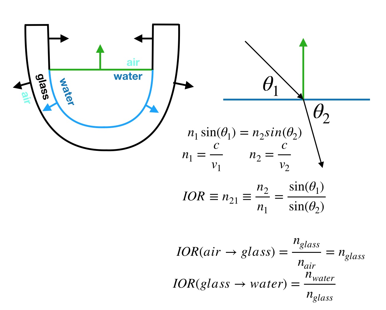
First we create a two coencentric cylinders connected at top and bottom then extrude and shape it
into a wine glass. We also create a face for the liquid surface.
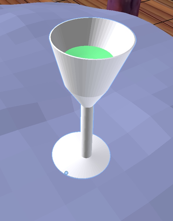
Bring up the settings with N and turn on the normal display, tweaking the normal vector lengths.
Note that normal vectors all point outwards from the surface by default.
Add a new Glass BSDF material with the color white, i.e. clear glass.
The index of refraction (IOR) = 1.5 [glass] / 1.0 [air] = 1.5, assuming outward pointing normals.
Give it a name WineGlass.
Select all vertices for the glass to air interface which are those on the outside of the
glass plus the inside of the glass above the liquid surface.
Assign this material to the vertices.
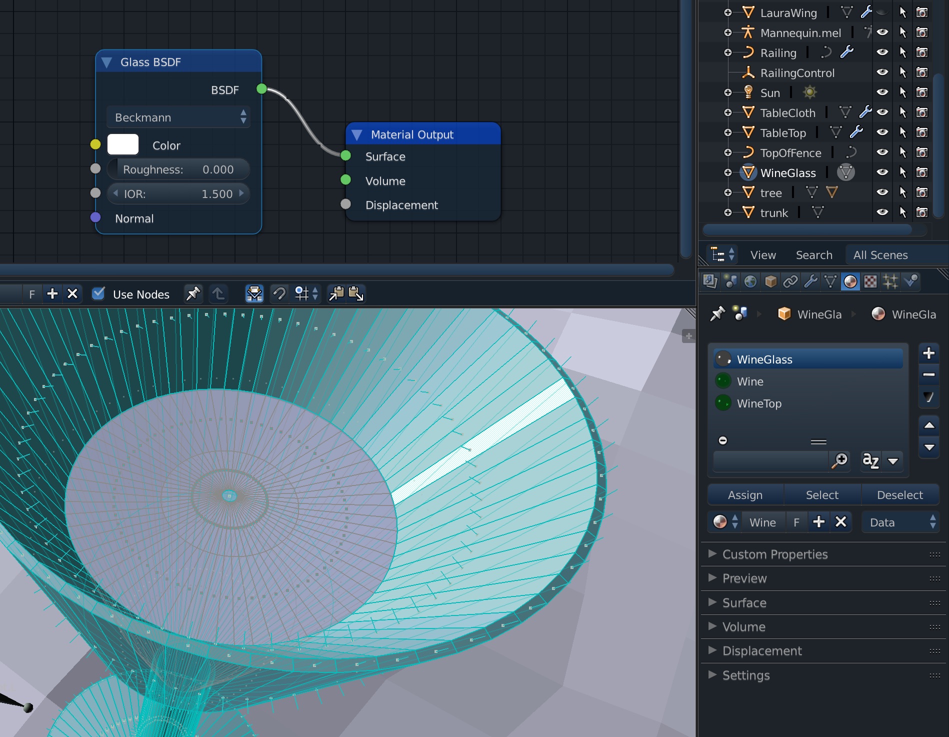
Create a new material Wine with IOR = 1.33 [water] / 1.5 [glass]= 0.8.
Select the vertices on the inside surface of the glass.
Assign the vertices to this material.
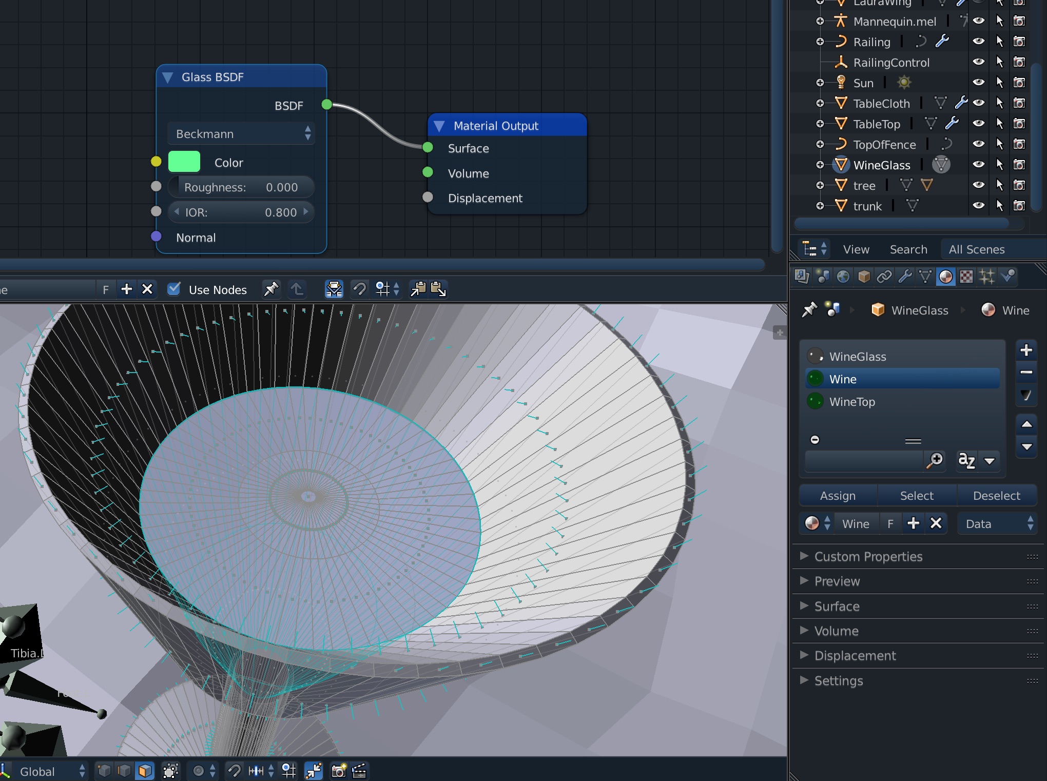
Create the final material Wine Top with
IOR = 1.33 [water] / 1.0 [air].
Select the top liquid surface.
Verify the normals are pointing upwards.
Assign the vertices to this material.
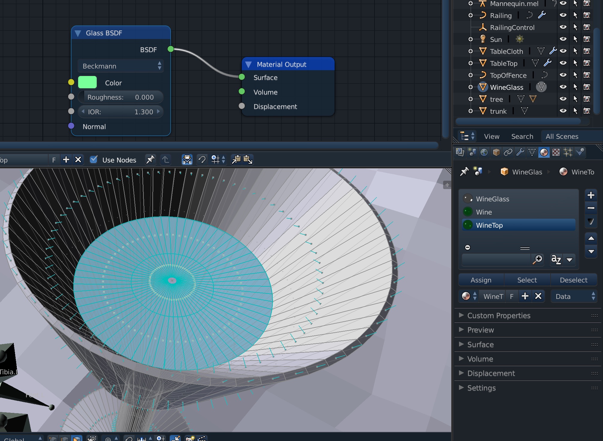
Do a test render,
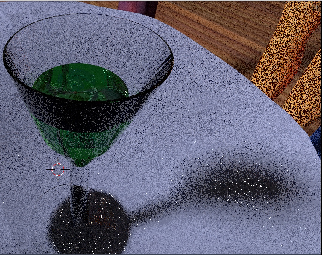
Table Cloth
We'll do a simple table cloth.
First create a simple plane with an opaque material,
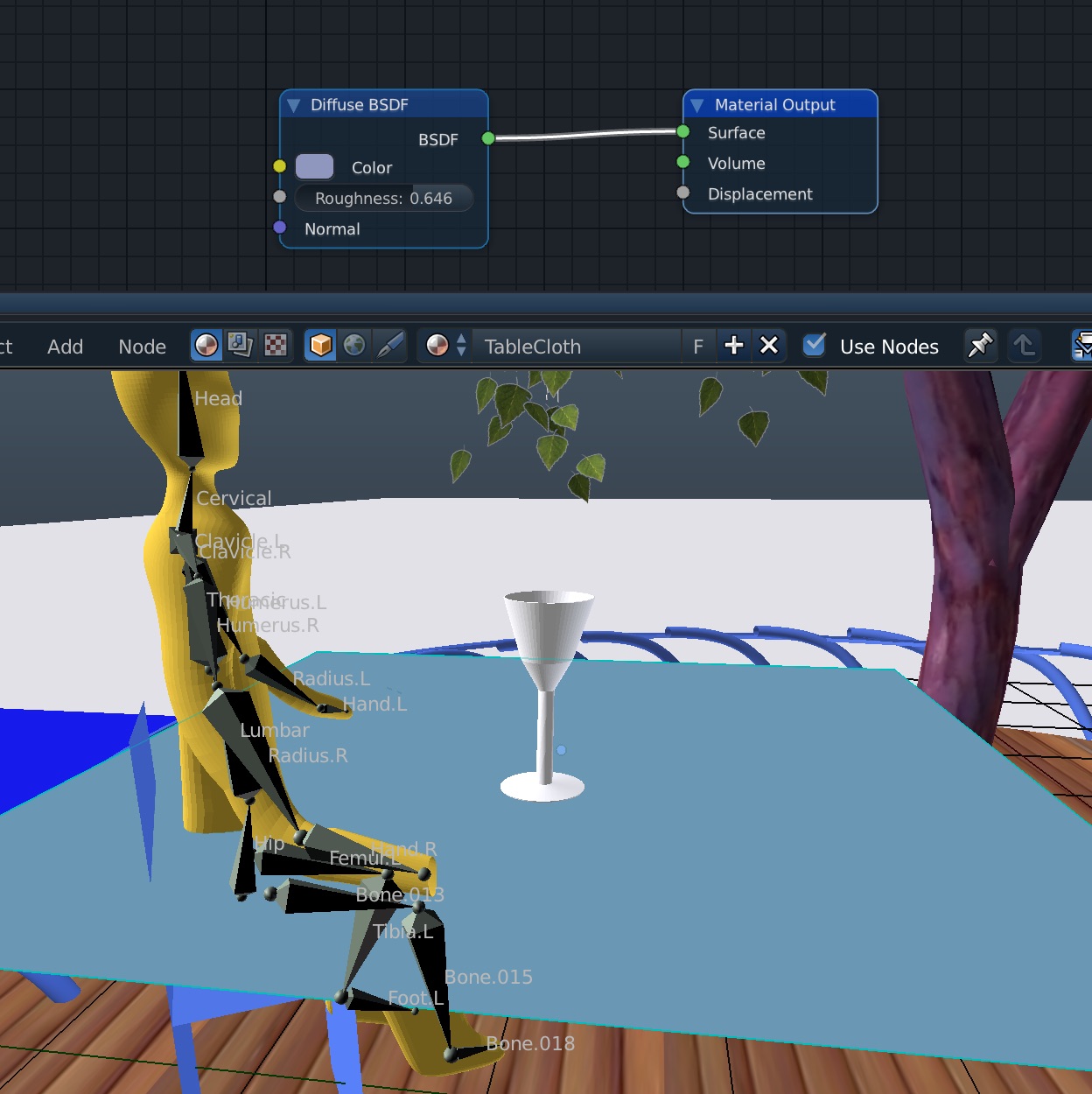 Then add a Multiresolution Modifier, subdivide a few times, then go into Sculpt Mode,
bring up a grab Brush, adjust its radius and strength settings and put wobblies into the cloth,
Then add a Multiresolution Modifier, subdivide a few times, then go into Sculpt Mode,
bring up a grab Brush, adjust its radius and strength settings and put wobblies into the cloth,
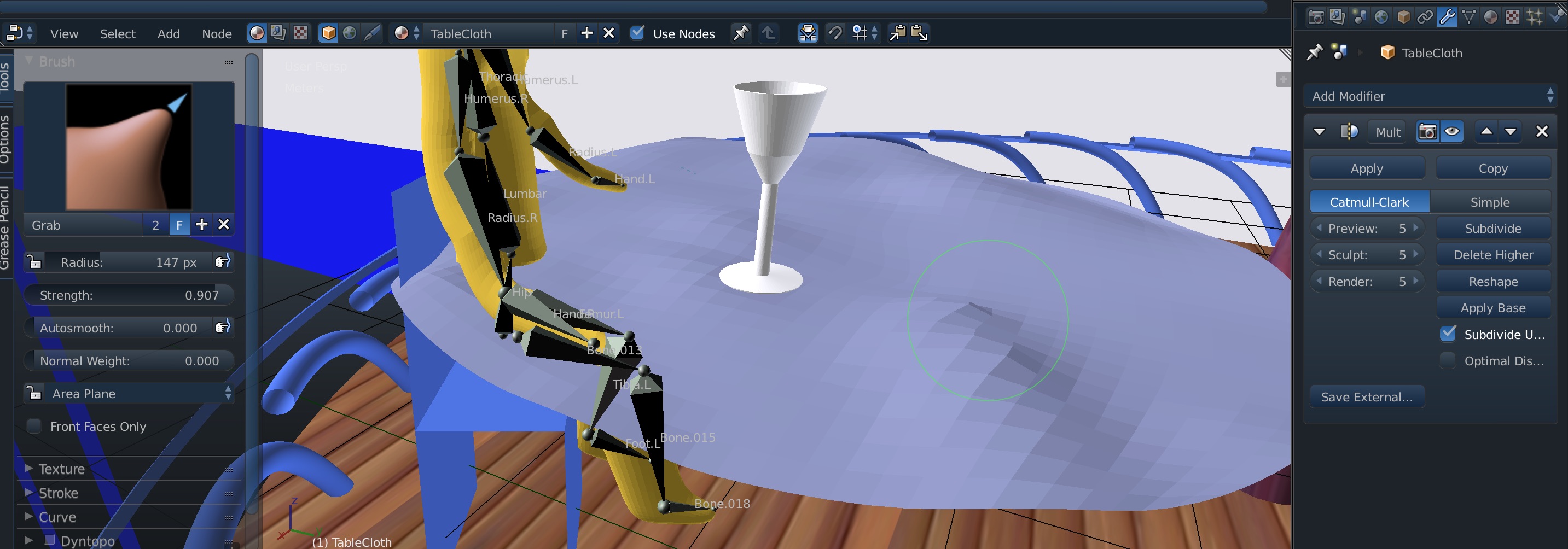 we'll add a Cloth Modifier
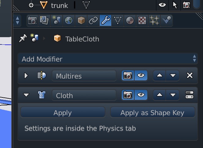 Adjust it in the Physics tab to do Self-intersection so the folds look right,
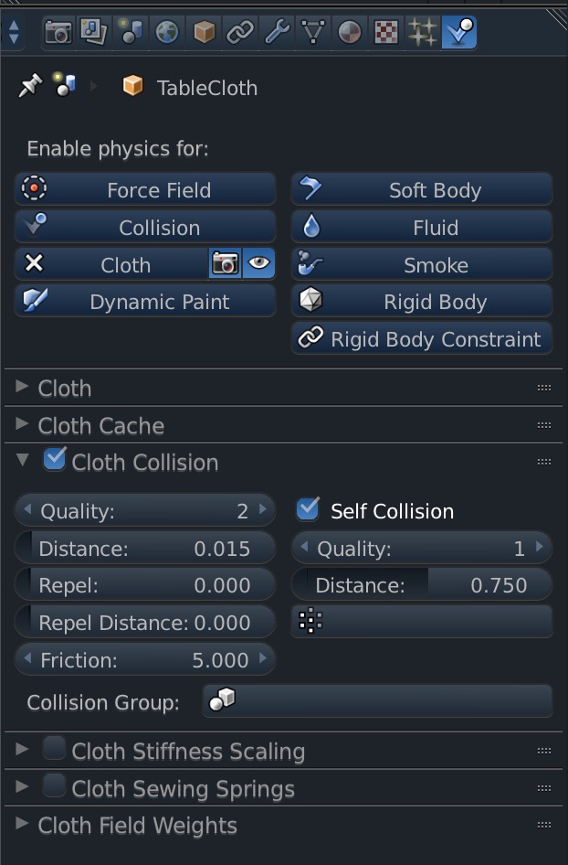 The table cloth must not fall through the table! Add a Collision Modifier to the table top,
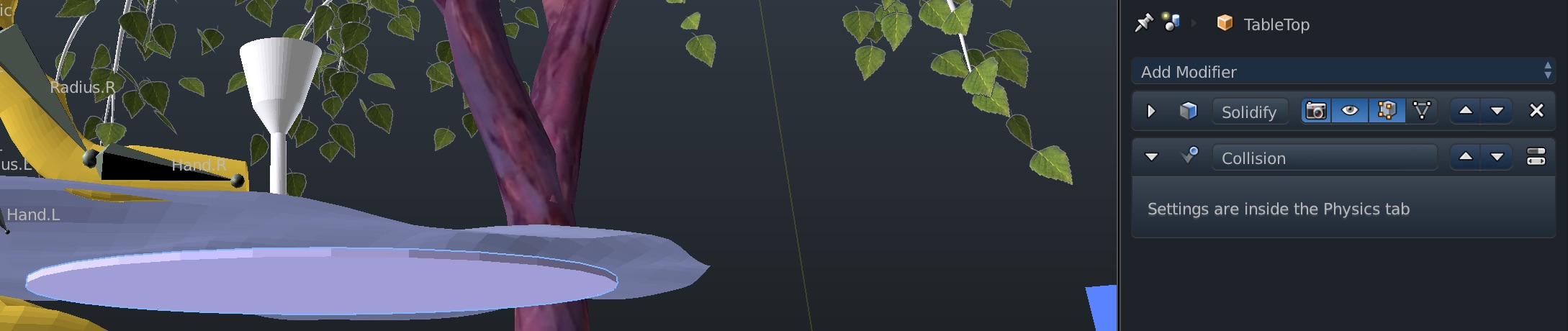 Blender has gravity turned on by default in the -z direction.
To engage the physics, and allow the table cloth to fall in folds across the table,
Play in the Animation panel,
Blender has gravity turned on by default in the -z direction.
To engage the physics, and allow the table cloth to fall in folds across the table,
Play in the Animation panel,
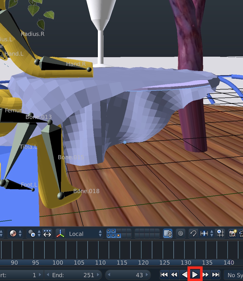 Here's our test render in the viewport,
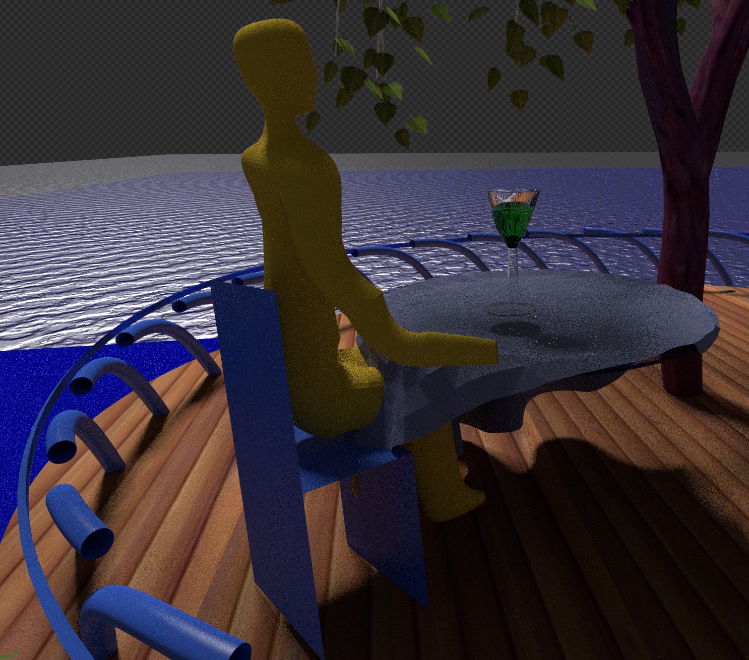
Ocean
Let's do a ocean! I based it on Create Large Scale Oceans in Blender 2.8 by Dylan Neill
First create a large plane 200m x 200m. Subdivide it with 64 cuts.
Add a Principled BSDF material node with no color (black). Since we have an air to water interface,
set IOR = 1.33 and 100% transmission, alpha = 1.0. Set roughness to 0 since the ocean modifier will provide the surface
irregularity.
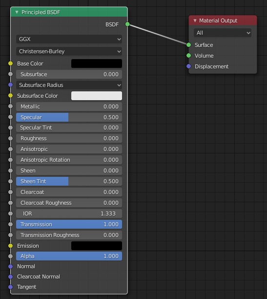
Add a Subsurf Modifier, then an Ocean Modifier.
In the Ocean Modifier set Geometry ➤ Displace since we'll be modifying
the flat plane geometry.
Resolution is cranked up gradually until we get enough detail in the waves, but not to slow down the
rendering a lot.
Spatial size = 200 to match the plane size.
Smallest wave = 0 so as not to smooth out detail. Play with alignment and
direction of the waves. Set Damping = 0.
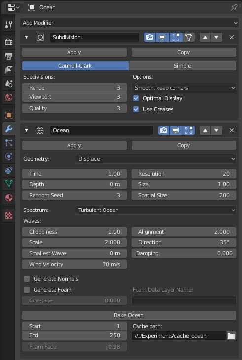
Adjust the world lighting in Look Dev Mode. Mine is very simple, just a single sky blue color which will
be reflected in the ocean surface,
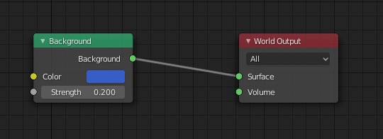 Do a test render,
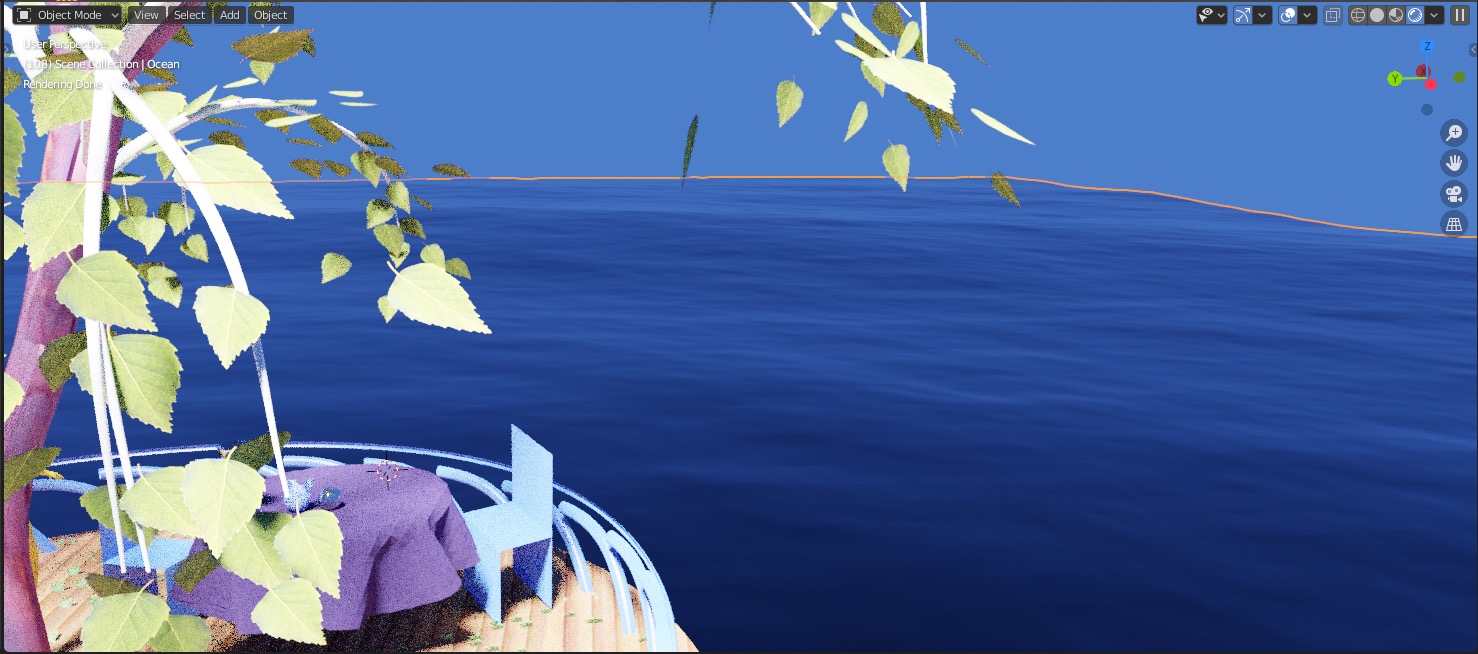
Compositing
Composition can denoise renders, tune overall colors and superimpose rendered objects over a painted background image.
It's done in the Compositing Workspace
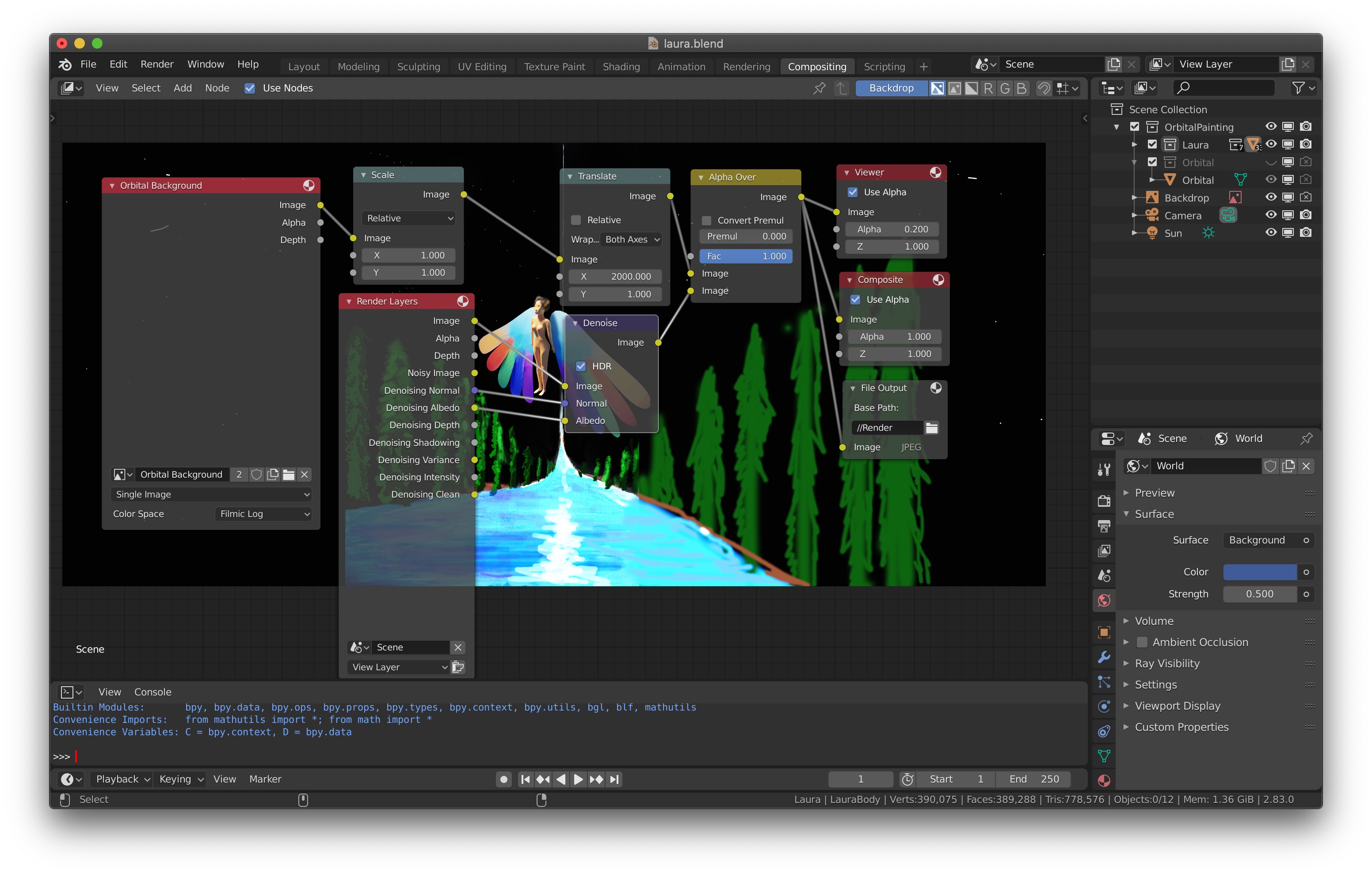
Background Image
We can do a matt painting for the background scene in Gimp to save rendering time for large and distant objects. This will let us do two things:
- While modeling, give us a background painting for reference before we do any rendering.
- After rendering, provide the background painting. The rendered view will go on top of it.
Create a new node using
Shift A ➤ Image ➤ Background.
Then load the image from file.
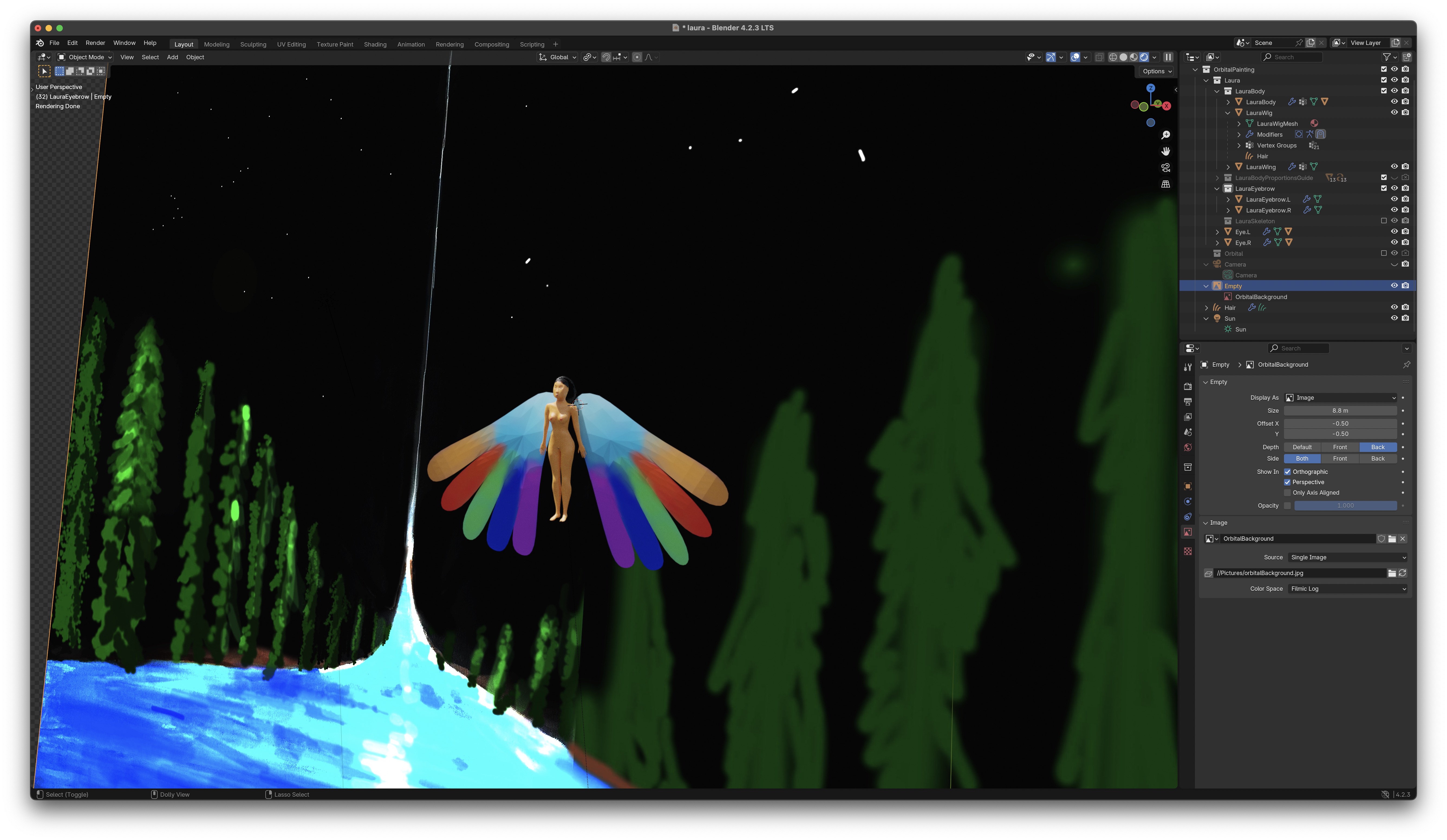
You can adjust the background image position, size and depth in the Properties Editor ➤ Object Data Properties
Composition Nodes
We are going to render our objects with a transparent background, so it can be placed on top of a background painting. Properties Area ➤ Render Properties ➤ Film ➤ Transparent We'll use the new denoiser which eliminates most of the speckles from the cycles render.
Scale and translate the background image until the render view is placed where you want it.
I've turned on Wrap ➤ Both Axes to make the image wrap around,
though it would work better if the image were periodic.
Use the Alpha Over node with Fac = 1 and
the render image in the bottom slot to merge the render image on top of the background image.
You'll need to send the final image to the Composite node to get the
rendered image; to the
File Output node to save the final image to file (note the relative path
//Render;
and to the Viewer node to see the result in this
Compositing workspace.
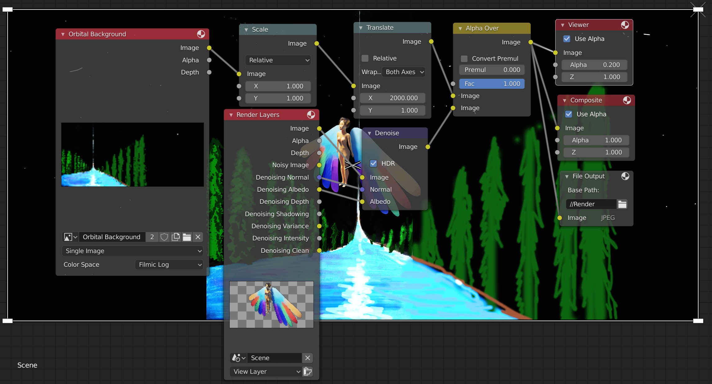
Rendering
Rendering the image with this button
 which will bring up a new window
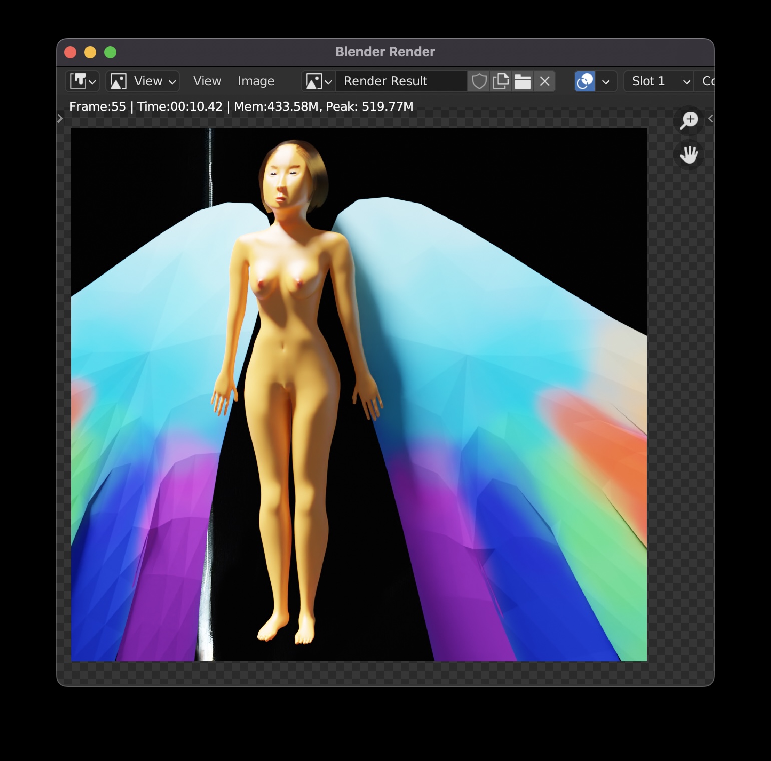 If you switch to the compositor, it will now show the complete scene.
To speed up renders, you can make sure your image size is no more than needed.
In the camera view, Ctrl-B drag mouse to create a smaller subwindow to
render in.
If you switch to the compositor, it will now show the complete scene.
To speed up renders, you can make sure your image size is no more than needed.
In the camera view, Ctrl-B drag mouse to create a smaller subwindow to
render in.
Building Blender from Source Code
Building Blender on Mac OS
Follow instructions in Building Blender for macOS
You can also build with XCode and do source level debugging!
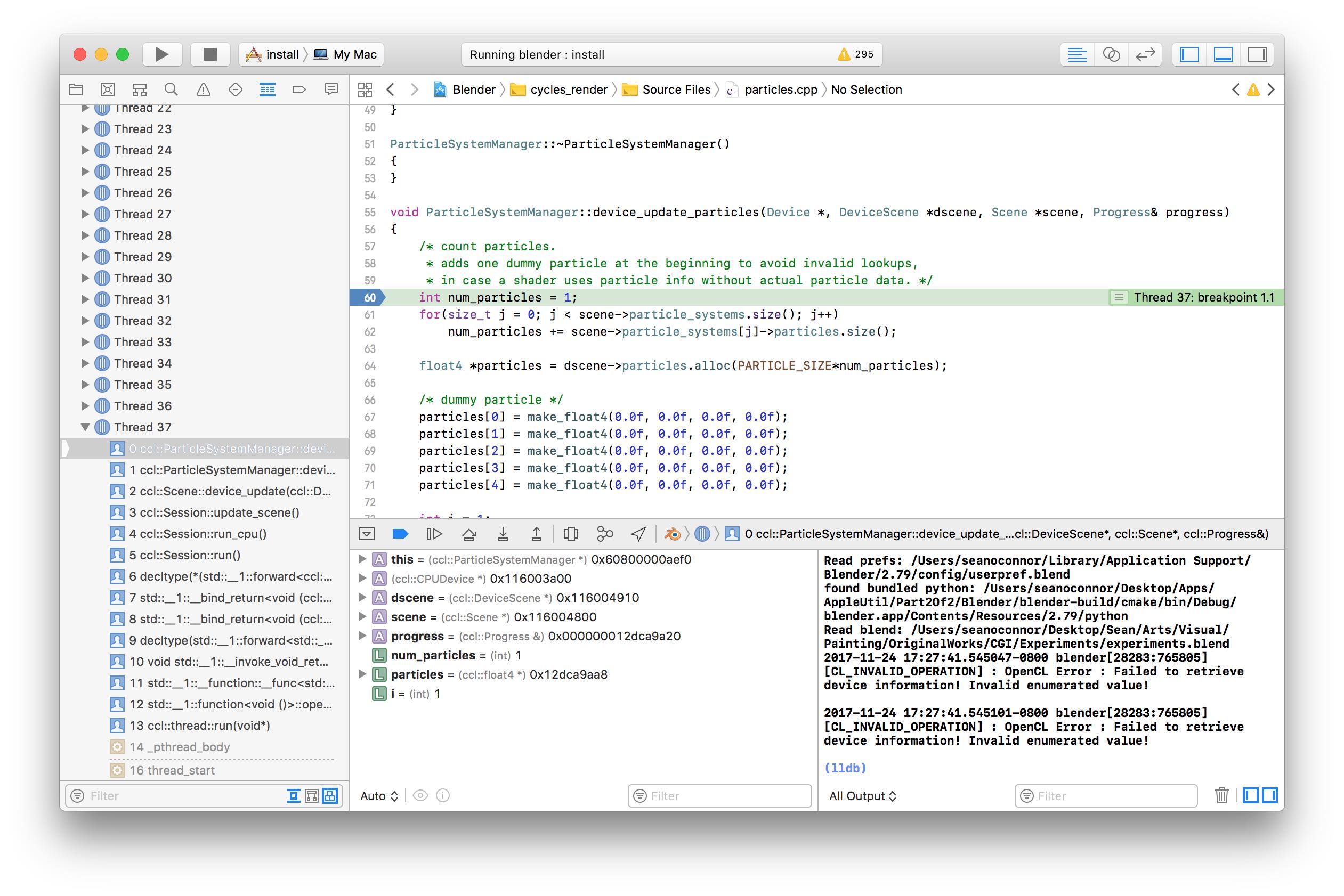
Building Blender on Ubuntu Linux
Follow instructions at Building Blender in Ubuntu from Source Code
Timing tests for Blender
| Cyberpower PC AMD, Ubuntu Linux 20.04 LTS (Focal Fossa), CPU render | 23 seconds |
| Mid 2015 MacBook Pro 2.5GHz Intel quadcore i7 16GB, macOS Monterey, CPU render | 22 seconds |
| 2018 MacBook Pro 15 inch 2.9GHz Intel 6-Core Intel Core i9, 32GB, macOS Monterey, CPU render | 19 seconds |
| 2021 MacBook Pro Apple M1 Max 64GB, macOS Monterey, CPU render | 8 seconds |
| 2021 MacBook Pro Apple M1 Max 64GB, macOS Monterey, GPU render | 5 seconds |
History
Original document written by Sean Erik O'Connor.